Pump up the charge: Getting -5V from a 5V power supply
When it comes to electronics, I am a woman of simple interests. Ideally, I only want to care about one voltage, and ground– there’s a reason I did so much better in my college digital electronics course than the analog electronics. But every once in a while you have to look at things more complicated than 1 and 0. Today, we’ll be looking at the most dreaded of all: -1. And it’s not balanced ternary. Can a simple IC save us?
Motivation: Arcades
What do the Sega System 1 and the Hyper Neo Geo 64 have in common? Here’s a hint: it applies to every arcade board I’ve talked about so far. It’s also something they have in common with your PC, if you don’t have an ISA bus.
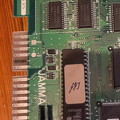
They don’t use negative five volts. This is particularly obvious on the MV0 single-game Neo Geo boards, as they replace the -5V pin on their JAMMA header with a little tiny “SNK” logo. Most boards that don’t use -5V will still have a pad there, but it won’t actually be connected to anything.
This is pretty convenient if you’re using a supergun like the Retroelectronik that I discuss in the article, as then you can use an ATX PC power supply, which are easy to get ahold of. In fact, I usually use a PicoPSU. However, ATX power supplies dropped -5V back in the early 2000s , and many had stopped providing that voltage even before then, as it hasn’t been needed on machines that don’t have ISA slots, and those were well on their way out by the late 90’s.
So, this is great! At least, for the boards I’ve used so far…
The Triple-Z80 and its audio friends
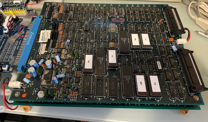
This is Athena, an SNK game from 1986. You might be familiar with the NES port, but I promise you, the game works better on its arcade version. It uses the SNK “triple Z80” board; so named that because it uses three Z80s. Two of these share the job of running program code; the third runs sound code. This board style was used by some other games, such as Fighting Golf.
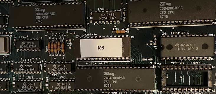
Using three CPUs is interesting, but let’s stay on topic. So, what does a board like this use -5V for?
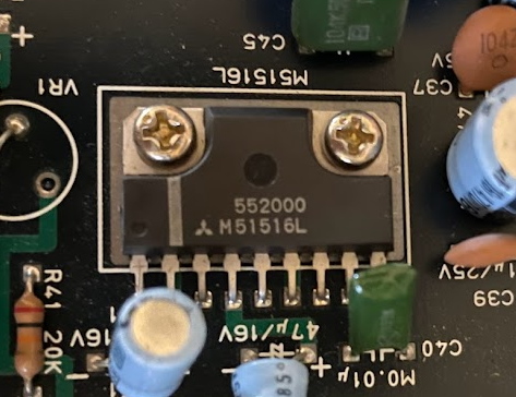
The Mitsubishi M51516L, a 12W audio amplifier. JAMMA boards use amplified audio that can be plugged directly into a passive speaker; it can be a real risk for supergun users, as providing amplified audio signals to a device expecting line-level can have explosive results. But let’s put that aside, and take a look at the pinout. This was hard to find; I eventually found it in a large PDF with hundreds of other audio amplifiers.
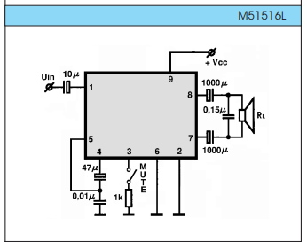
And that amplifier doesn’t use -5V on any listed pin, right?
Well, while you may not see it on the diagram, when I beep out the circuit using a multimeter, I see that the -5V passes through a 100uF capacitor, and then goes into pin 6 and pin 2. What are those pins? They’re the ground, of course. By setting the ground to -5V, they can use 12V on the pin 9 for +Vcc, and have a whopping 17V between ground and positive voltage. This is great for an amplifier, since the larger the input voltage range, the more you’ll get of an output.
By comparison, the Sega System 1 (specifically, my copy of Pitfall II) uses a similar 12W LA4460A amplifier but can only max out its supply voltage at 12V; therefore, your Athena machine might end up being louder, and therefore SNK might be able to attract a few more people to play their platformer instead.
But what happens when there’s no negative voltage? Well, in that case, there’s no ground. And that’s not good for the amplifier; I’m not sure if it’ll damage it really since current can’t flow without a ground, but you’ll get a much worse fate: Athena without sound.
Turn that sign upside-down
Well, the smart thing to do here is to buy an arcade power supply. In my case, I’m in a stop-gap situation where I’m waiting for an order to complete, but due to all the fun that is buying bespoke-made products in 2021, you get stuck waiting for awhile. It would be nice to have a stopgap I could use to create -5V.
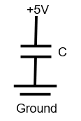
Let’s look at an incredibly simple circuit. This is just a voltage source, a capacitor, and ground. Since the voltage source is DC, this will “charge” the capacitor: One side will have a higher voltage, so electrons will be pushed away, leaving positive charges. On the other side of the capacitor, electrons will be attracted to that positive charge. (The ground is basically a source of electrons, or a place where you can dump them. Its voltage will not change. Of course, this assumption can break down once you start having real power)
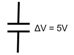
So what if we immediately disconnected the capacitor from the rest of the universe, including its power supply and ground? Well, if we did that after the capacitor was charged, we’d find a differential voltage on the power supply. What if we hooked up ground to the side that had +5V before?
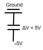
As you can see, the difference would be flipped. We now have a source of -5V. Of course, it will only last as long as the capacitor has charge, but if we can switch back to the first configuration, we can then build up more negative charge. In a sense, we’re “pumping” the charge– this is a charge pump. You can use transistors as switches here so you don’t have to constantly disconnect and reconnect wires.
Caveats
All analog electronics are dangerous. In this case, you’re dealing with low voltages, so the personal danger is probably relatively low. However, it is always non-zero!
Using a charge pump on your +5V line will draw its current from that positive +5V line. Make sure your power supply can handle this. Again, the best option is to use a proper arcade power supply. This is a stop-gap for me.
Using -5V for an amplifier is generally a more tolerant of errors or fluctuations than using -5V for RAM chips. While I don’t know of any JAMMA boards that use -5V RAM, that doesn’t mean they don’t exist. Use at your own risk!
Many arcade boards that require negative voltages, like the SNK Triple-Z80, are quite old and easy to damage. Test everything. Use at your own risk!!
The circuit
Of course, constantly switching voltages by hand would get tiring. So that’s why we have integrated circuits to do it for us: in this case, the ICL7660.
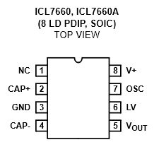
This provides the pump. We still need to attach a capacitor across CAP+ and CAP-, and hook up a supply voltage. It’s also a good idea to attach a capacitor between the output and ground to reduce the “ripple”; since we’re constantly charging and discharging the capacitor, there’s going to be some AC fluctuations. LV is used for low voltages, and the data sheet says to leave it disconnected above 3.5V. OSC can also be left disconnected. (I recommend looking at Peter Vis’s circuit)
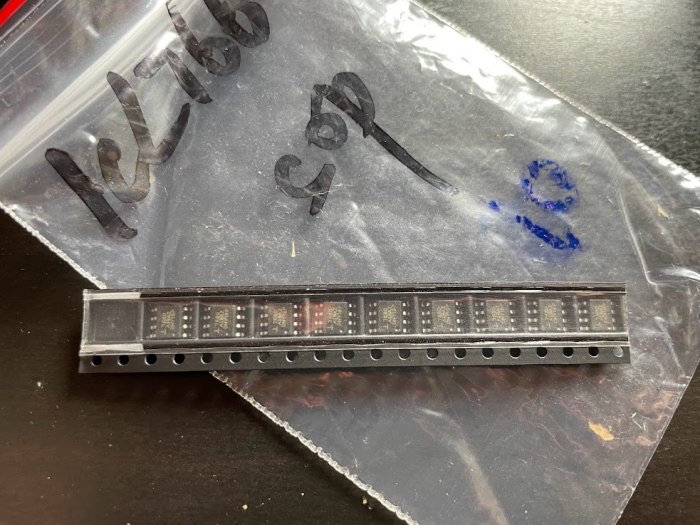
I should note that I was a silly person and ordered the chips in SOP8 form factor. If I was a robot, this would be very nice, and you can see they even arrived in the package for a pick-and-place machine. Thankfully, I had spare adaptors I could use on a breadboard, but if you want to build this circuit, then I recommend just buying DIP8. Or being a robot. That might make other things easier too.
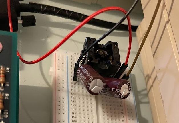
Check the output using a multimeter before hooking it up to a board. But for all this analog complexity, the circuit really is that simple.
And… yeah!
Now I can hear the audio of Athena. And to me, game audio is really a huge part of the experience. It’s worth noting though that for this use, I noticed that -5V plummeted down to -3V; even for this use case it’s having a struggle to provide the full -5V. That’s fine for this amplifier, but it might not always be. And also note that this won’t be enough amperage to run the amplifier at full power; I keep the volume low here (the board has an adjustment potentiometer) and amplify it at my speakers.
Still, I think this was fun as a very simple project. For little analog issues like this, there are chips out there that can help you out! The major problems have frequently been solved by someone else.
It’s worth noting that -5V doesn’t always mean 1980’s games. Midway continued using that point well into the 3D era. It’s still part of the standard today for JAMMA, and there’s no promises that any random board won’t use it.
