Composite Modding another Atari, because Colors are Hard
Back in 1978, I took a look at the Sears Tele-Games Pinball Breakaway, a rebadged version of Atari’s Video Pinball (the home version), whose chip was also used in one of the variants of Epoch’s TV Block. A lot has changed since 1978, and one of those things is that RF modulators just don’t cut it.
Here it is

As a refresher, the Pinball Breakaway is a woodgrain masterpiece powered by a single game-on-a-chip. As far as I know nobody has decapped it to confirm, but given its 1978 release it’s likely a microcontroller running an internal ROM of some sort. But that’s all locked in a chip, which is locked in a silver box.

We won’t bother with that because the RF modulator is out of the box. And the Pinball Breakaway is seemingly built for repairability; all the buttons not mounted to the PCB, the speaker, and the spinner all use detachable and color-coded connectors inside. Even the RF cable is internally detachable. The 1970’s really were a different world.

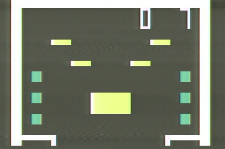
Why do I want to do this? Here’s a picture I took back in 2021 1978 for that linked post above.

And then this picture I took later, with the same RF2AV box.

These have completely different colors. Both are plausible enough, I suppose. And some elements on the screen change colors when you hit them. But still, more different than I’d expect, for the same console going through the same RF2AV box.
Moddery
The Tele-Games Pinball Breakaway shares a similar characteristic to the Pong Sports IV I composite-modded during the Pong console series: both require AC coupling. Finding which pin is which on the RF modulator isn’t hard; the top pin is clearly on a ground plane, the middle pin can be traced directly to the 5V power regulator, and so by process of elimination…

I couldn’t find my electrolytics, so I decided to try with a ceramic capacitor (using the same THS7316 video amplifier, but since the Breakaway uses a 5V regulator, I just ran the amp at 5V), and I just got this output out of the Koryuu:

There is some color, but it’s just rainbow banding. The Trinitron did do colors, but it didn’t match my past screenshot of the system over the RF2AV box. The datasheet diagram says to use an electrolytic (or at least a polarized), so this is my fault. That being said, the only improvement I was able to get in the color department was by snipping the lines leading to the RF modulator; at least this made things a little brighter, always nice.

The Koryuu has very little configurability, so I switched over to the Micomsoft Framemeister. That’s right, after all my mocking of its composite input, where do I go? Crawling back to Micomsoft.

Now that’s more like it! But it’s different than either of the patterns above, and even less like how it looks on my Trinitron with the same mod. What gives?

If you’re wondering what the low-end white AV2HD box I used in the composite comparison post does, it makes even less sense. Kind of reminiscent of the old RF2AV screenshot, though.

Oscilloscope traces
When you can’t determine the color in a composite video signal, the most likely culprit is the colorburst. The color burst is a 3.57954MHz signal which synchronizes color; color is determined by the phase shift of a signal relative to the color burst. I talked about this in the composite video.
Here’s a functional colorburst from my Panasonic FS-A1F MSX2 computer. The signal drops in the horizontal blanking interval, and then the colorburst happens before the video signal proper starts. Here the screen happened to be all black, and it’s NTSC-J, so there was nothing afterwards.

And now here’s the colorburst on the Pinball Breakaway. The yellow trace is the output of my AV mod, the blue trace is the input, because the signal was so bad I wanted to make sure it wasn’t the mod’s fault.

That is a very ugly color burst! And the signal appears to be filtered so heavily that it’s not even fully risen from the horizontal blanking period. If that first pulse of the color burst isn’t detected, then the colorburst will be out of phase, and given the phase determines the colors, well, you can imagine what happens.
Here’s the color burst for the Apple ][. I think anyone who complained this signal is out of spec needs to apologize.

Who knows what is real
The Atari Video Pinball manual is in full color, and seems to correspond to the colors I’m seeing on the Trinitron– blue paddles, yellow and green bumpers. That makes sense; the PVM is after all a professional-quality device.

I do have a theory for why the signal is like that, though. Take a look at the signal through an S-Video cable’s luma input.

Notice the left side is not nearly as clear in colored areas– there is some very aggressive filtering on the signal. Perhaps I should take apart my TV Block and give it the same treatment; I’m not even sure if that thing works, though. Or even build a new circuitboard for the C11500-03 chip. Probably overkill; I can just play on the PVM.

