Interlacing, Deinterlacing, and Everything in Between
So in some of my recent posts, I complained about interlaced graphics. But interlacing is actually a pretty interesting topic, and solved a good problem! Why did people in the analog era put up with this? Why doesn’t it look as good on modern screens? This started out as an aside in an upcoming post, but quickly got out of control– so let’s dig in!
Motivation
The first thing to note about analog television is that the standards we’re talking about were developed in what, in electronics terms, was the Dark Ages: vacuum tubes, not transistors. Printed circuit boards weren’t used and all wiring was point-to-point. Capacitors were still called condensers. So a lot of the systems were designed around technical constraints that just wouldn’t be as relevant.
To note: the 525-line “System M” television system, which gave us the signal timings I’ll talk about, was introduced in 1941. The European system, which adapts similar signals to 50 Hz frequency, came after World War 2. And those were latecomers; television in the 30’s had even fewer lines.
But what is a “line”? For that, we need to look at what a Cathode Ray Tube is. Don’t worry, we won’t dig into the electronics. The main thing you need to know is this:
CRT 101
A Cathode Ray Tube (CRT) is an overgrown vacuum tube, one end much wider than the other. At the narrow end, it fires a stream of electrons to the wide end. The electrons hit the wide end, which is coated in a “phosphor”, which is a chemical that glows when it gets hit by electrons. Since electrons have a negative charge, the beam can be moved.
For television signals, the beam doesn’t just move around freely. (That’s how vector games like Asteroids work, though) It moves in a particular pattern called a “raster”, following one line to the next down the screen, and then back to the top.
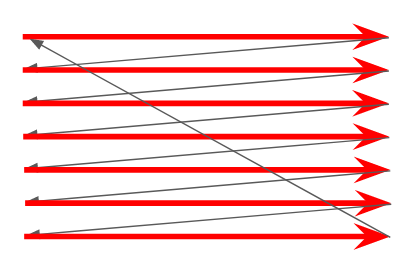
We hit a strange truth about analog monochrome television: the vertical resolution is strictly limited: it’s the number of lines you draw. But the horizontal resolution, the resolution within each line, is basically infinite; it’s a purely analog signal. The only thing that holds it back is how quickly the electronics in your television can keep up.
And that is perhaps the dark secret of CRT televisions: if you could freeze time, you could see that at any given instant, the only thing lit up on the screen is a single dot. That dot just constantly moves, and the image processor in your head turns that into a picture. You can contrast this with an LCD television, where if you froze time, you could still see the whole frame just fine.
This is why CRTs can be so hard to photograph, and it’s also why CRTs wear out. The phosphors are basically being constantly blasted with electrons; eventually, they won’t emit light anymore, and given that they’re on the inside of a sealed glass tube, there’s not much you can do to fix that.
An aside: Phosphor delay
So, what I just mentioned about seeing a dot when time is frozen? That was a bit of a simplification. See, when the electron beam hits the phosphor, the chemical reaction takes some time, and light can continue being emitted. How long the phosphor keeps glowing after being hit can vary a lot.
So, what happens if you use a long-lasting phosphor? You might think that’d be better. But as it turns out, the lovely Monitor /// that has made many an appearance on this blog has exactly that! Long-lasting phosphors were frequently used in the 80’s on monitors that would spend their lives displaying text; it was seen as less stressful on the eyes. (As a child of the 90’s, I definitely remember being warned of the eye-straining effects of CRTs)
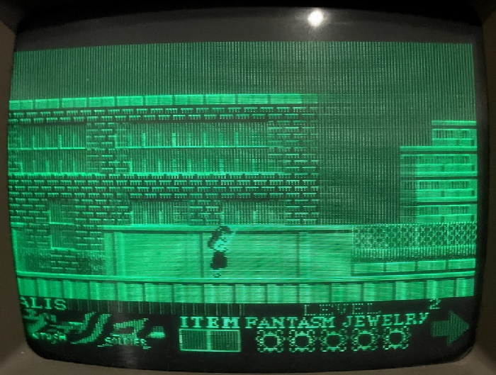
But while that’s fine for text, as you can see, it just doesn’t work when things start moving. Moving objects leave visible trails; that’s not just a photographic effect here. (Valis: The Fantasm Soldier is particularly bad because the screen does not scroll smoothly; see the brick wall above Yuko) When television was developed, moving pictures was kind of the whole point. Television phosphors, therefore, are generally short-lived.
Time and time again
So, here’s a trick you can do. Take an LED and turn it off and on at 60 Hz. It’ll look like it’s always on; in fact, incandescent lights plugged into North American AC power do exactly that. Now, turn off and on the LED at 1 Hz. You can very easily tell that it’s turning off and on. No coincidence there; that’s exactly why common home AC power frequency is 50-60 Hz; you can’t go much lower than that, or the human eye will start to notice you’re playing tricks on it.

Let’s look at that raster scan again. If you’re drawing part of the screen, you better get back to that part of the screen and draw it again before the eye notices. That is to say, the field rate, the rate at which drawing happens across the screen, must be that same 50-60 Hz. In fact, for interference reasons with old electronics, the television standard developers wanted it to be exactly that.
The fastest reliable screen rate that the developers of the television standard in 1941 could get with electronics that could be consumer-viable was around 15kHz; specifically, 15.734 here in North America was chosen, allowing 262 lines within 60Hz. Some of those lines are used up for the “blanking interval”, which is when the TV returns the beam to the start of the next field. Therefore, you get 240p.
240p
240p is the resolution that gave us every NES game. Every Neo Geo game. Every PC Engine and TurboGrafx game. The vast majority of Genesis and SNES games. So you’d be forgiven for thinking it’s good. But television wasn’t designed to throw sprites around. It was designed to film the real world; and the real world has a very high resolution.
So to get a higher resolution, there are two interesting problems that have to be solved:
- You don’t have a transformer that can draw horizontal lines faster than 15kHz
- You have to draw something at every part of the screen at 60Hz, or the image will flicker
Behold, Interlacing!

And that’s where interlacing comes in. The field rate remains 60Hz, but on every alternate field, you draw slightly offset. This doubles your horizontal resolution (twice as many lines), but you only draw a full frame every 30Hz.
What does 480 lines get you? Here’s an image of my cat, half the screen has 240 lines, the other half 480 lines. (Note that the horizontal resolution is 640 pixels in both cases, to simulate the “infinite” resolution of an analog signal)

It’s particularly obvious on his face.

And that’s really all there is to interlacing. Drawing the fields like this gives you a nice resolution bump, and on CRT TVs, it’s trivial to support both interlaced and “progressive” scan signals; the famous game console 240p just doesn’t do the offset. (This is why some CRT TVs will show “scanlines” on game consoles but not on regular TV signals)
30fps? Not quite
So, interlaced signals are often listed as their frame rate. “480i/30”, for example. This seems obvious; I just said it takes two frames to make up a field, after all, so isn’t the animation rate of an interlaced signal half of that?
No. Interlacing has another trick up its sleeve, and it’s one you get “for free” in the real world. A television camera (as opposed to, say, a film camera) is just a television in reverse. It’s constantly scanning what it sees in a raster pattern. So when it starts scanning the next field, time has passed!
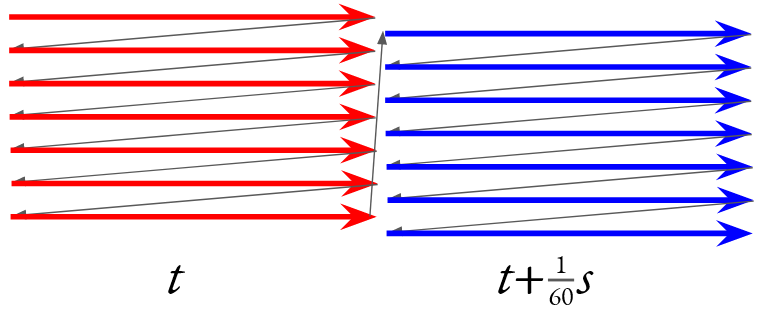
An interlaced frame is not a progressive frame; it’s two frames, but only half the information on each. If an object moves, it will move on every field!
This is where the image processor in your head comes into play. Remember, all the CRT is really displaying is a very fast-moving dot. So the lines from the previous field have started to fade by the time the current field’s lines are drawn. Even better, your mind’s eye is really good at interpreting movement, and is used to moving objects having less visible detail.
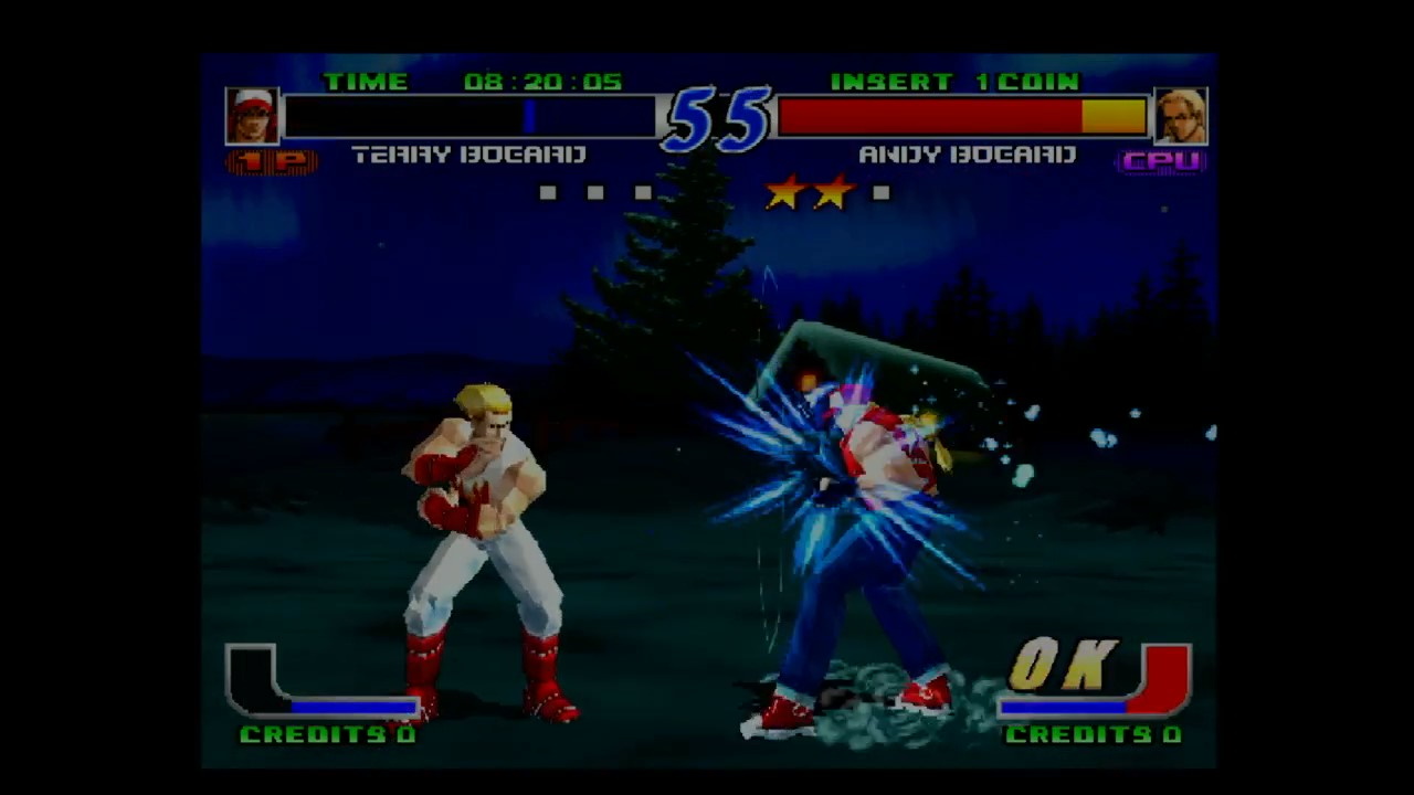
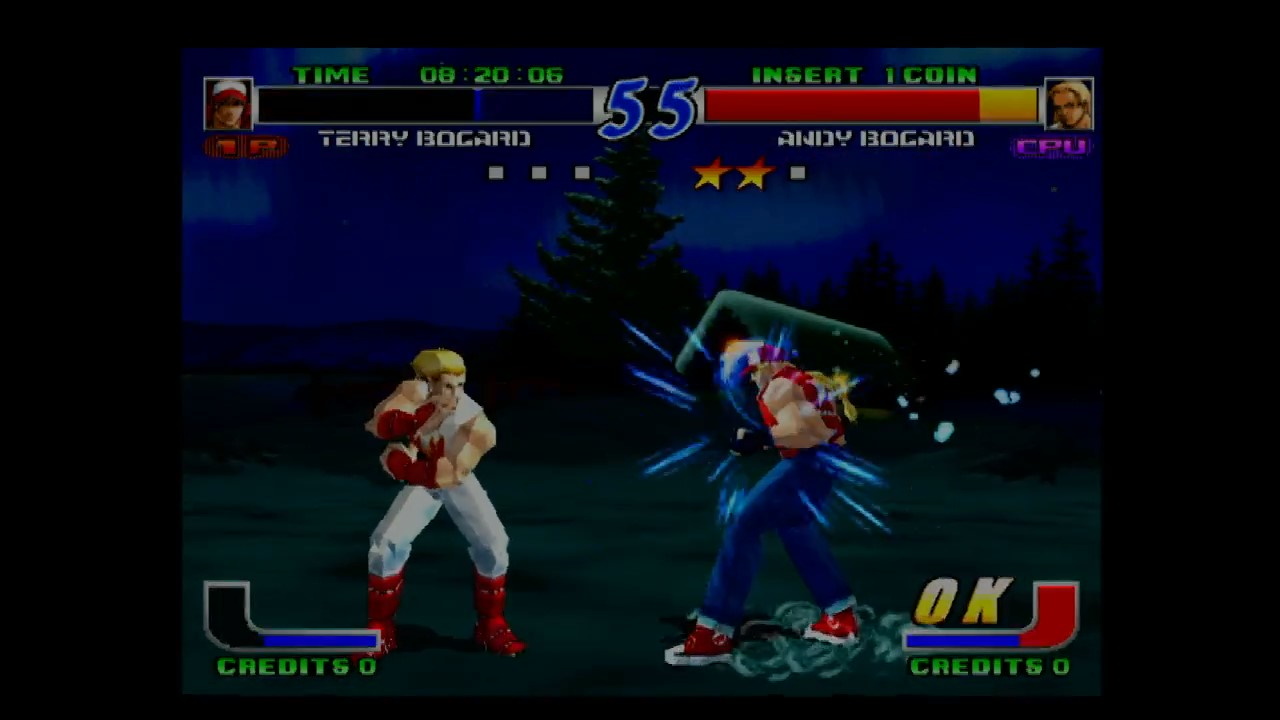
Take these two instants from Fatal Fury: Wild Ambition. Look at the box surrounding the avatars at the top to see that these images were each derived from two different fields, yet Terry Bogard moves horizontally between the two.
Thus, an interlaced 480i/30 signal is not the same as a 480p/30 signal. An interlaced signal can provide more information about motion, at the cost of providing less detail for moving objects; which in the real would would be obscured by motion blur anyway. And it’s a simple, analog process.
De-interlacing
So, now we reach the problem: we’ve moved to flat screens. And these screens draw the entire image at once, using various methods. But as noted, we can’t just take one line from each field and alternate them, because they’re at different points in time. In fact, let’s drive that home.
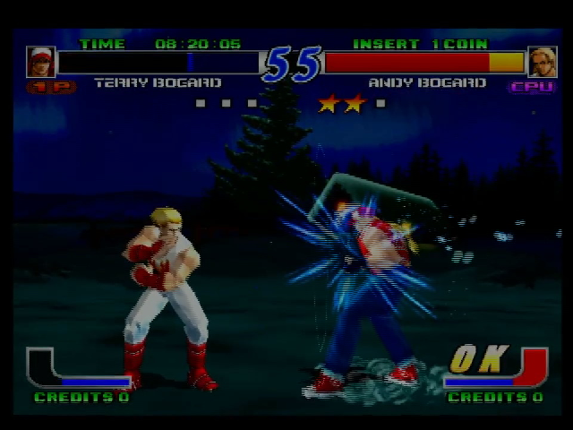
Notice that anything that moves between fields now gets covered in a swarm of lines. And all of these lines are visible at the same point at the same time; your brain can’t trick itself into thinking this is just motion blur. This is the tell-tale sign of bad deinterlacing. (It’s particularly bad here because I’m interlacing two image captures, but it gets the point across)
Still, deinterlacing can be done. Indeed, many HD television broadcasts are 1080i, to reduce the need for additional over-the-air bandwidth. It’s likely that you didn’t notice. It’s also likely, though, that you did notice that there was a bit of a wait to change channels, that isn’t there otherwise.
Lag-free deinterlacing
Now, deinterlacing isn’t the only thing causing that inter-channel delay. But it definitely doesn’t help. But it doesn’t matter; you can have entire seconds of lag when watching broadcast television and you’d never know the difference. Your spoilers on twitter will seem to be just in time with everyone else’s.
Yet I just posted images of a fighting game with interlacing. Sure, Fatal Fury: Wild Ambition isn’t the fastest-paced game in the series, but still, lag can be noticeable. And it’s not the only example of a game where lag can make a real detriment to the experience.
Bob
The most common solution in enthusiast devices, including that used for the screenshots above (taken with the Micomsoft Framemeister), is Bob deinterlacing. Surprisingly, not named in honor of Mr. RetroRGB.
Bob deinterlacing ignores that the images are slightly offset horizontally entirely; it just doubles each line, and treats it like a 240p signal. This produces a bit of a “bobbing” effect at 60Hz, but on the right TV, at a far enough distance, if you’re not too sensitive to it, this is basically the perfect deinterlacing.
For “line-doublers” like the OSSC, this is really your only option. It’s also the only truly lag-free option.
Motion-adaptive deinterlacing
The other way to deinterlace is to take into account moving objects. This requires image processing to determine what’s moving, and what’s not. This, of course, will add additional lag, but it doesn’t need to be a lot with a fast chip and a smart processor.
A potential downside of this is that it can be hard to determine what exactly is moving. For example, take this screenshot of the Commodore Amiga Workbench UI scaled by a GBS-8200, a cheap scaler frequently used in arcade LCD conversions. (This was produced by my Amiga 1000)
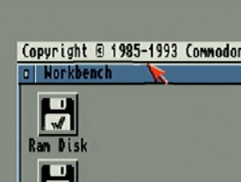
Notice that the area around the mouse, including parts of the Workbench titlebar, are distorted around the mouse cursor; this is because I was moving the mouse cursor at the time. You can literally see the screen shift around it. Even worse, this image shouldn’t have been deinterlaced at all; the GBS-8200 deinterlaces any signal you give it, even if it’s progressively scanned.
GBS-8200
But let’s give the GBS-8200 a chance with 480i. After all, if you see Fatal Fury: Wild Ambition in an arcade today, there are decent odds that the owner cheaped out on a CRT repair and is using a GBS upscaler on the image. And you should still play it, because any arcade operator keeping the Hyper Neo Geo on circuit definitely needs the quarters.
As an aside: the GBS-8200 is popular with arcade operators because it can take signals directly from a board, without the need for a supergun. But I will be going through a Supergun to make the situation equivalent; additionally I am using a SCART-VGA converter on the input (just changing the signal levels, no processing) and a VGA-HDMI converter on the output for capture.
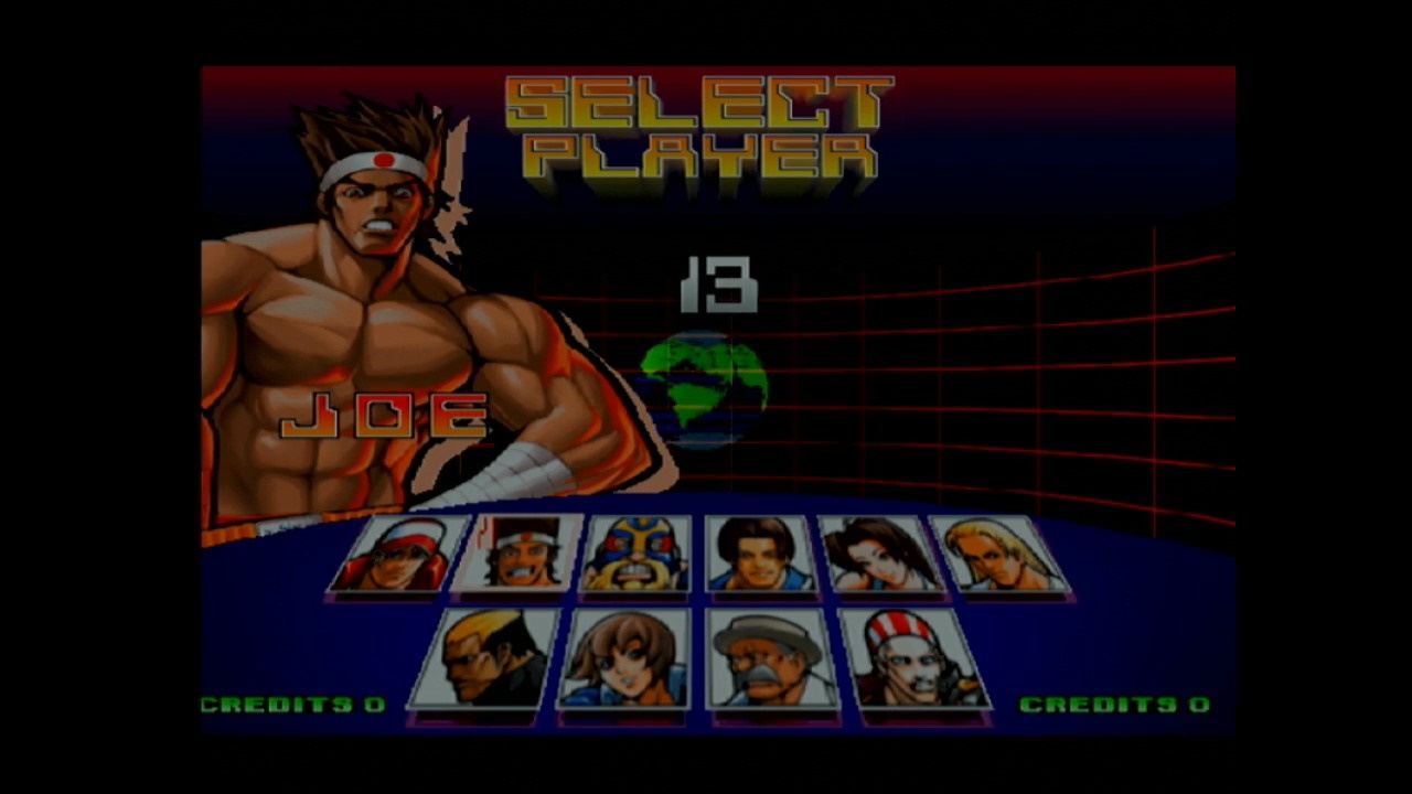
The GBS-8200 to my eyes gives a bit of a rounded effect, almost like a 2xSAI filter in an emulator, but it does handle still images like the character screen pretty well. Notice the thin black lines around the name “JOE”, for example. (Ignore the slight crop at the edges, that’s because this outputs a 16:9 signal and my capture card is trying to fix that)
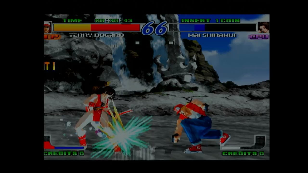
In gameplay, though, you can see shifts in the background, and even the static areas, like the “CREDITS” text, are muddy and not very crisp. Even worse, though, look underneath the attack’s flash, and you can see what look like vertical deinterlacing artifacts; the deinterlacer is struggling to deal with flashing effects. Given how common those are in games of this time (often in lieu of proper transparency), it’s pretty disappointing.
I don’t have the proper equipment to measure lag; I did lose earlier than I expected, but I’m not great at video games, so we’ll say it’s fine there too.
Micomsoft Framemeister
Shockingly, the Framemeister has this capability! Indeed, part of the reason I’m making this blog post is because I totally neglected to take this into account in my reviews before.
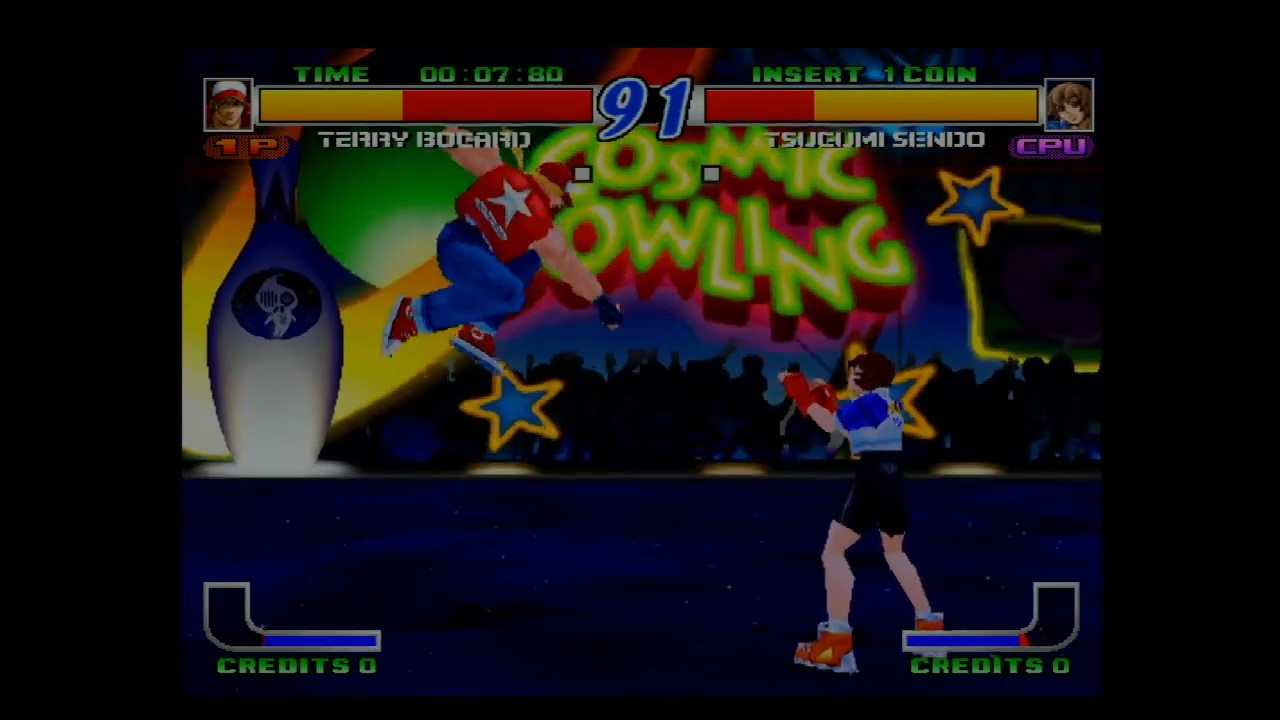
Take a look at the UI, especially the health bars. You can see a lot more detail in a still; these areas don’t move around at all during battle, unlike in the bob deinterlace modes. You can compare the word “CREDITS” to the GBS-8200 screenshot above and see how much clearer things get. On the Framemeister, the “Game” modes use bob deinterlacing; these screenshots were taken in “Anime” mode.
As you might expect for anime, this provides a major improvement on the still character portraits. Take a look below; left Terry is in “Anime” mode with motion-adaptive deinterlacing, and right Terry is in “Game 2” mode, which has the same color and other settings as Anime mode, but with bob deinterlacing.

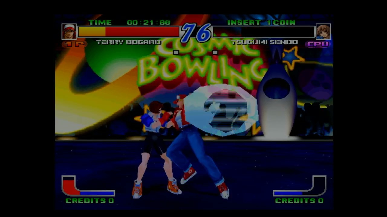
That being said, even such an expensive device can’t deinterlace perfectly on the fly. For example, look at Terry’s “Burn Knuckle*. There’s that tell-tale line pattern clear as day.
GBS Control
So, this deserves a blog post of its own– and that one’s over here. The GBS Control is a setup that attaches a new microprocessor to the GBS-8200 board, and uses it to control the GBS’ image processor, the Tvia Trueview5725.
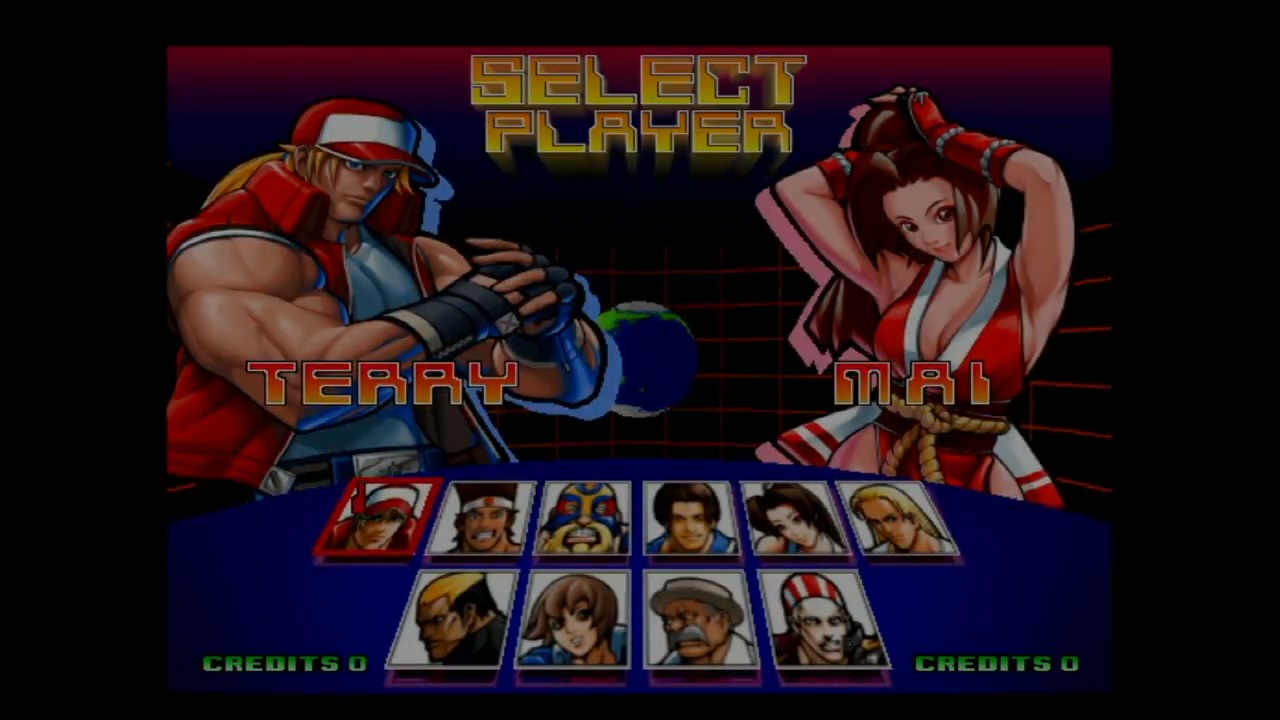
As expected, it does very well on the character select. It seems the custom software gets rid of the smoothing effects, which in my eyes is a very welcome change. Indeed, comparing Terry to the Framemeister screenshot above, I think his image looks a bit cleaner, though I could be seeing things.
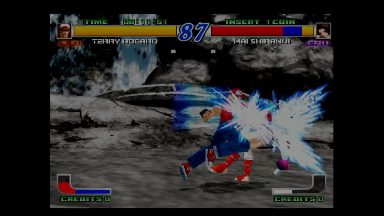
You can see the tell-tale deinterlacing lines, but it was harder for me to find than the stock GBS-8200 firmware. Still, the Burn Knuckle is a dead giveaway, just like the Framemeister. And like the Framemeister, the new firmware also makes the static text, such as “CREDITS”, much more readable. So it’s a clear improvement.
Honestly I’m impressed here; the GBS Control does a great job deinterlacing and I would say it’s on par with the Framemeister; even if you buy a premodded unit, the GBS Control is much more affordable than the Framemeister these days; since its discontinuation prices have gotten way higher than I would expect anyone to pay.
“Objective” tests
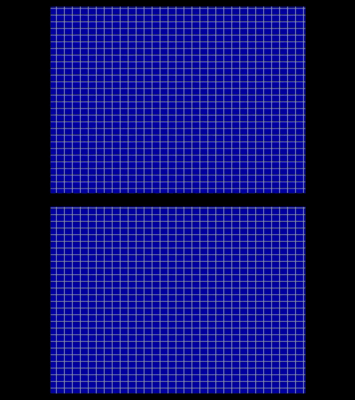
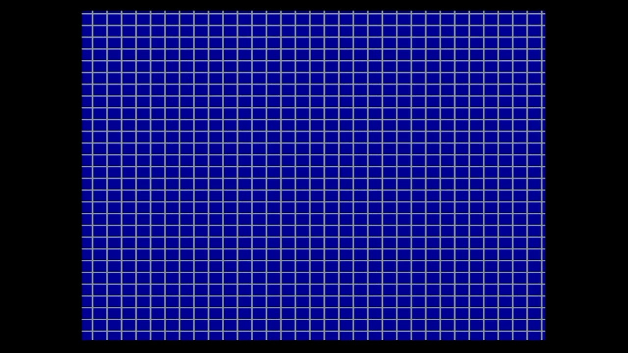
The Hyper Neo Geo 64 boots up and shows a grid pattern. So I figured it might be interesting to show it in different deinterlacing methods.
Bob deinterlacing (Framemeister “GAME2”)
Bobbing slowed down because I don’t want to give people that much of a headache. You can speed it up to 60Hz yourself if that’s what you want.
GBS-8200 (standard firmware)
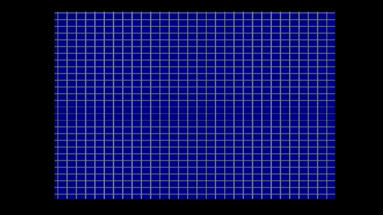
Framemeister (“ANIME” preset)
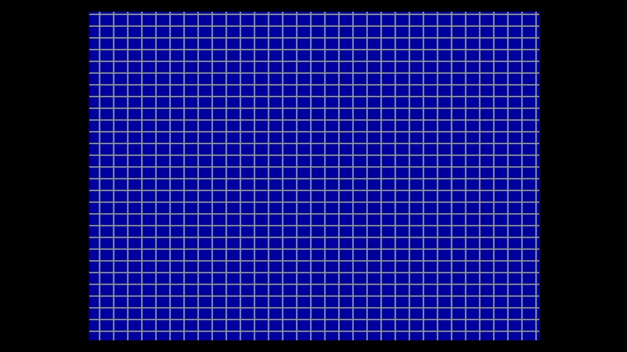
GBS-8200 (GBS-Control firmware)
Interlace me, cap’n
So the main reason I made this blog post was because of things I noticed while looking into deinterlacing techniques; it really gave me more respect for interlacing as a concept. It’s actually a pretty clever solution to the problems of the past! But the past is where it belongs.
I’m also very impressed with the GBS-Control’s deinterlacer; if you’re playing a lot of 480i games, especially 480i arcade games, on a CRT, I think I can wholeheartedly recommend it. The OSSC is the usual recommendation as a Framemeister successor, but since it only has Bob deinterlacing, it’s good to see an alternative. Just a shame it has no composite input; I’d like to see how it handles Laserdisc video.
Also, technically, you can’t see anything when time is frozen. The light will never reach your eyes. Sorry.
