Upgrading the Atari 130XE Keyboard! DecentXE
One of the very first posts on this blog is on the Atari 130XE. The Atari 8-bit computers had some seriously impressive technology (remember, they came out in 1979!), the missing link between the Atari 2600 and the Commodore Amiga, and by rights, the 130XE, the highest-spec version released, should be the best. But it was also released at a time that 8-bit computers were the cheaper alternative to Atari Corp.’s already-cheap ST line. So that comes with some consequences.
The 130XE
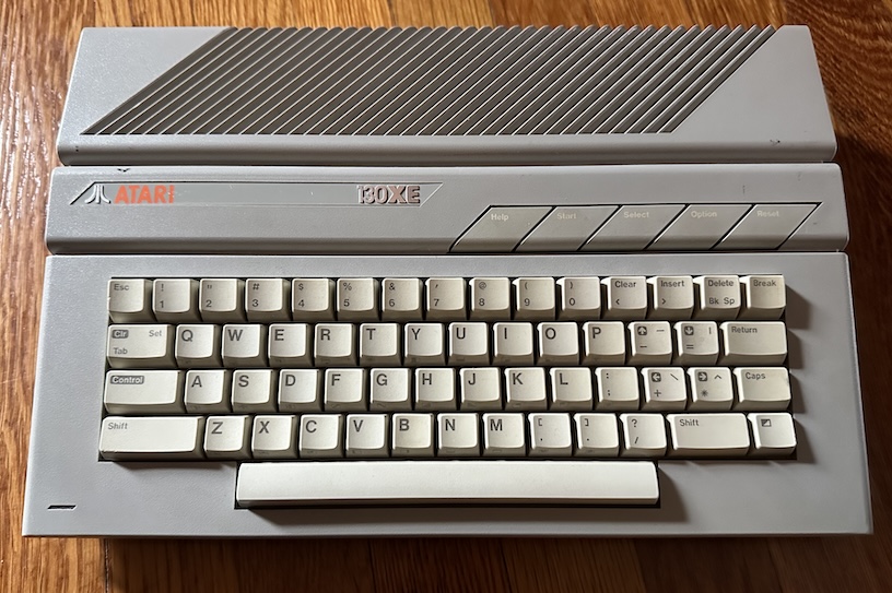
The Atari 130XE isn’t, on the whole, a bad-looking computer. But I’ll admit I prefer the look of the earlier XL machines, with their black, metal and beige, to the XE’s “ST baby brother” look. But it’s not the aesthetic we’re here to complain about today. It’s the keyboard.
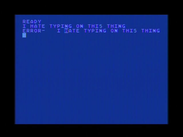
It’s mushy. It’s a dome over membrane, which means you have to bottom out on the switch to get it to register, but it’s so mushy that it’s hard to tell when that’s actually happened. Poor keyfeel aside, I have missed keystrokes a plenty when typing on this thing, and that’s just no fun to use.
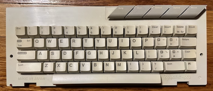
The Atari 130XE keyboard is a detachable module plugged in by a ribbon cable that’s actually part of the internal keyboard membrane. It also includes the power LED and the row of option buttons at the top right.
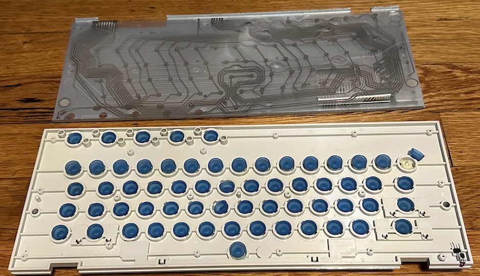
Taking out the million tiny screws that hold the module together, you can see that it’s a rubber dome over membrane keyboard, just like… almost every keyboard these days, really. Rubber dome keyboards can be fine, like Topre’s Realforce, but it really depends on the quality of the rubber, and this keyboard is just mushy and unpleasant. (I wonder if replacing these domes would be sufficient to improve things, but today we’re being more dramatic than that.) Also, look at that LED module in the lower corner; it actually contacts with exposed pads on the membrane.
Now, let’s be clear here: this isn’t the worst keyboard on an Atari 8-bit computer. That honor goes to the Atari 400. But hey, nobody’s releasing a mini XE, so who’s laughing now?
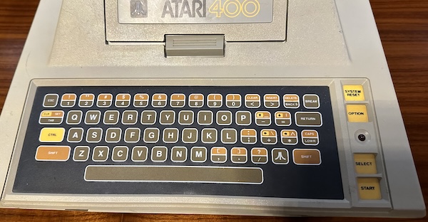
It’s nobody. Nobody’s laughing. Let’s get to the kit. And a huge shoutout to Jan Beta; I won this kit in a giveaway he hosted, and he’s already built one of the DecentXE keyboard upgrades on his YouTube channel. I hear people are into videos these days?
You might also be interested to know that the DecentXE project is entirely open hardware. So I might talk about some things, but remember that I have a particular pre-made kit. If you want to build one of these things, you can go wild.
A diversion on Keyswitches
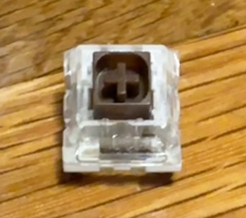
The DecentXE kit I won came with these: Kailh “BOX” brown switches. These are in the Kailh “BOX” family, which means the actual mechanical contacts are imprisoned inside a tiny plastic box, with a little plastic actuator that the keycap mount pushes on from the side. This helps make them more resistant to things getting in the switch and causing corrosion, in theory.
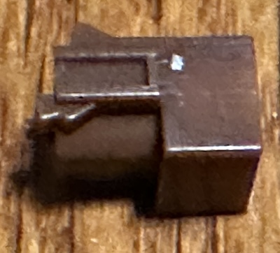
What makes these switches brown is that they’re colored brown, probably by a dye in the plastic. And the reason they’re colored brown is to denote that they’re “tactile”: the slider has a little dent in it, which means as you press it it feels a little lumpy. This lets you know that you’ve actuated it, in theory. In practice, my typing must be too heavy-handed, because they just feel like linear switches to me.
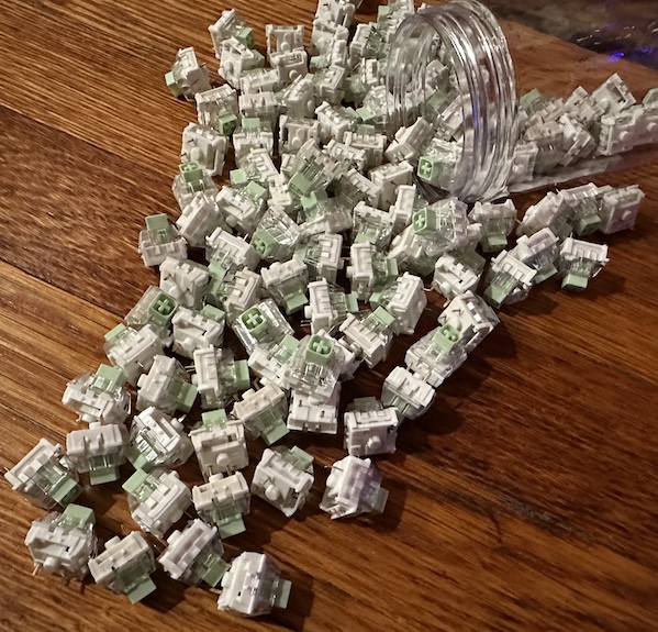
So I’ve decided to replace them with these: Kailh Jade “BOX” switches. They still have the protected box, but they also have a little metal “click bar” which doesn’t just make a tactile feeling, but also makes a loud audible click. After all, I’m not bringing this 130XE to the office. I don’t even go to the office. I work from home.
Here’s what the “boxes” of the two look like. Note that while the actuators are colored to go with their respective switch, there’s no difference inside the box. You can also clearly see the metal click bar; notice that it doesn’t actually do anything for the switch itself mechanically. Contrast that to, say, the IBM Buckling Spring, where the sound of the buckle is the sound of the keyswitch actuating.
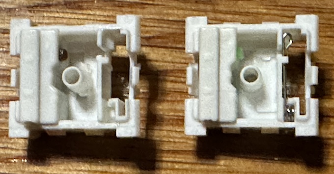
That gap is for PCB-side backlighting, which this keyboard does support. We’ll have to make sure to install the switches in the right orientation. I believe the DecentXE should support any “Cherry MX”-type switch, but I didn’t look into it that deeply. So now that we’ve figured out our switches, let’s dig into the actual kit itself.
PCB and plate
I keep thinking of these as two PCBs, but they’re not; they’re a PCB and an aluminum plate for mounting the switches into. This is a bit more secure, so they won’t move around much. If you’re going to all the trouble of installing a new keyboard, it might as well be a nice one.
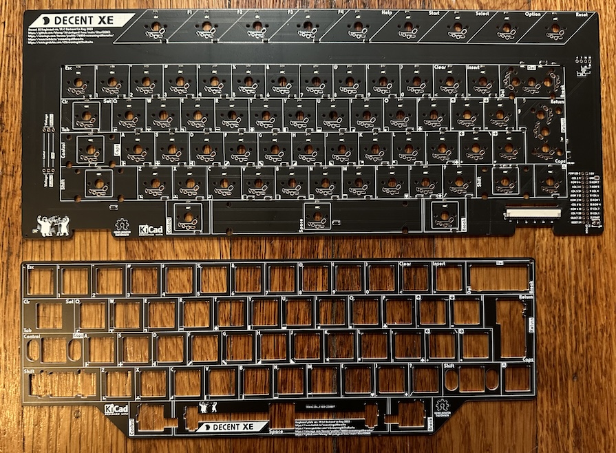
The keyboard PCB has a number of surface mount parts, but they’re all already installed, which is pretty convenient. One thing you might notice are the row of keys at the top extends further than the 130XE:
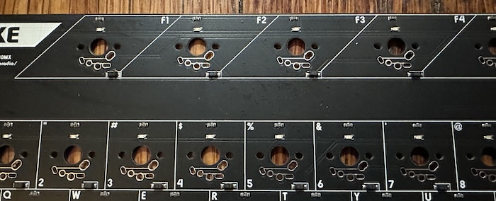
These F1 through F4 keys were only present on one model of the Atari 8-bit computer line, the Atari 1200XL. They have some cursor functions, but aren’t heavily used, because the 1200XL was one of the less successful models of the lineup. The function keys are also output to a pin header off to the side, but I’ll just be ignoring them. I guess they would help the “Baby ST” look go even further, though.
Step 1: Installing the stabilizers
You might know stabilizers as those annoying metal wires that make it a pain to take off spacebars, but this keyboard uses the more enthusiast-friendly “Cherry-style” stabilizers, which have little keycap mounts. Note that they don’t actually have any springs in them, just the metal linking wire that causes the whole key to move in unison. All the actual spring behavior comes from the keyswitch that will be installed in the center. Cherry has been known to use specific keyswitch variants with stronger springs just for the spacebar to handle the extra weight, but most rarely bother today.
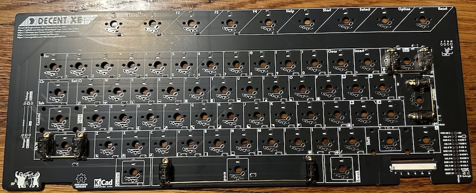
These just snap in on one side, and then the other side is screwed in. While there seem to be holes for the stabilizers on the right shift, this kit doesn’t include a stabilizer for that spot, and the keycap for that position doesn’t have anywhere for the stabilizer to attach. I guess it’s just there for options.
Step 2: Set the jumper
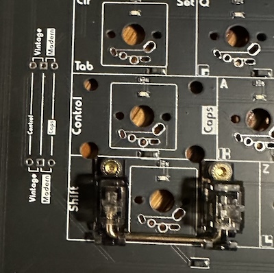
This is a very multi-purpose PCB (as you can probably tell by the many options for switch holes), so there are some jumpers that need bridging. Since I’m using a modern layout, these need to be jumped horizontally for “Modern”– basically, this lets you choose what this key above the left shift will be. I suppose HHKB fans will set this to Vintage.
Step 3: Install the switches in the plate
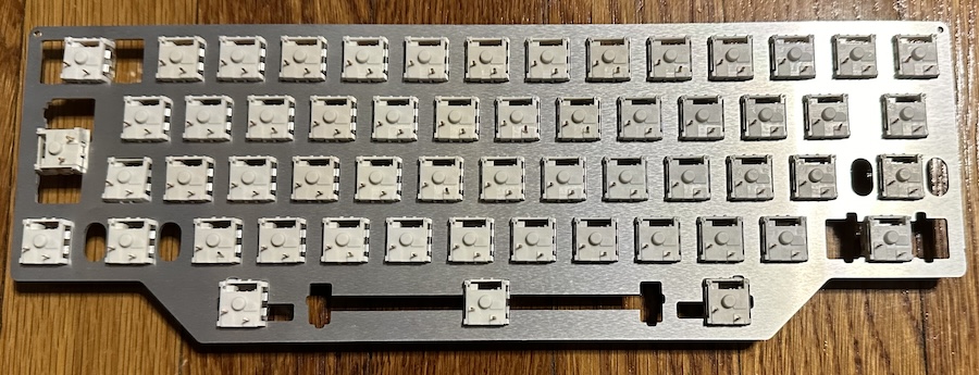
The switches simply click into the alumininium plate. Note that they can click in either way, but the orientation does matter– the pins need to be at the bottom, while the holes for the LED light to shine through need to be at the top.

The kit comes with a separate 3D-printed plate for the various control keys. These also require low-profile switches rather than the standard-height ones; as a result, I decided to just stick with the brown switches from the kit. The keyfeel of these don’t matter as much.
Note that the 3D-printed plate is a little bit thicker than the aluminium; it also has cutouts on the bottom to dodge surface-mount components on the board, which are convenient for orienting it. Unfortunately, this does make soldering it a bit of a pain, since the pins don’t make it all the way through the PCB now.
Step 4: Soldering
Honestly the hardest part here is orienting the plate onto the PCB so that all of the switches pass through. Anything that’s slightly bent will not line up, and every since switch needs to. But once you get past that, it’s just simple through-hole soldering.
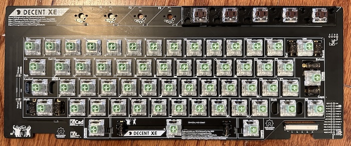
Step 5: Attaching to the Atari XE
As seen above, the Atari XE expects a fairly thick ribbon connection. This type of cable was integrated into the membrane, but now we no longer have a membrane. Meanwhile, the DecentXE PCB was designed to use a modern ribbon cable with much narrower pins. The solution here is to use a specially made flexible PCB.
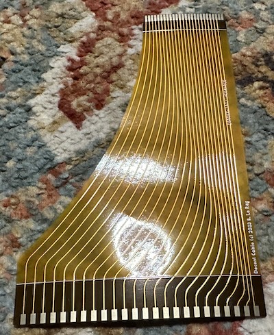
Honestly this was actually the hardest part; the connector on the DecentXE-side is very finicky, since you have to route it through the board– it might even be easier to install before the switches. I get the benefit of using a standard ribbon width and connector, but I do wish that this was a little easier.
Eventually, though, I got everything attached, and was rewarded with this:
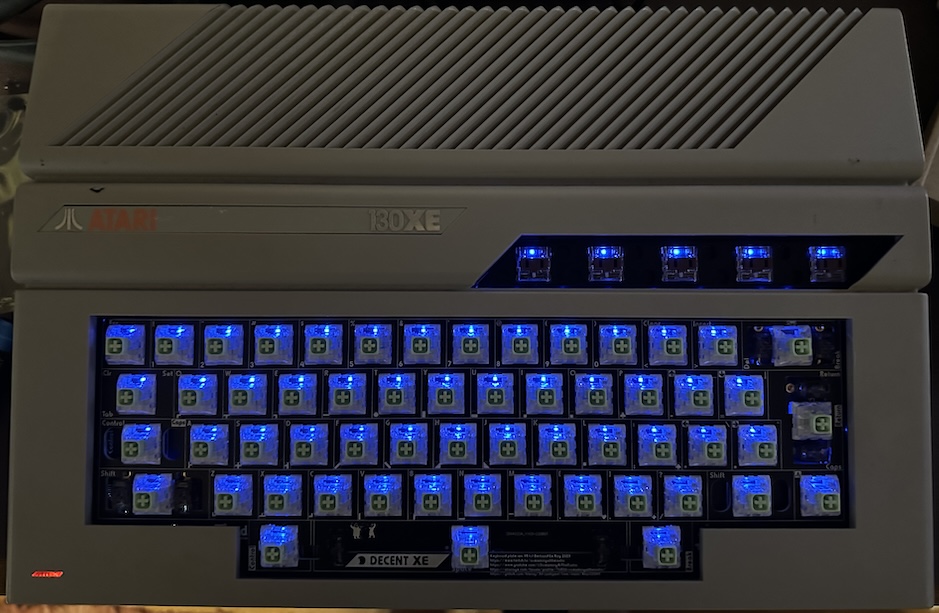
The Atari XE BIOS has a self-test (access by typing ‘DOS’ in at the command line without a drive attached, or by holding ‘OPTION’ while turning on the power) that includes a keyboard test. This is very useful for making sure everything works now; I’d do this before adding the keycaps just in case.

Step 6: Control key keycaps
The main keycaps are a solid set from WASD Keyboards with custom printing, but the various buttons at the top row are slanted, so you need custom keycaps. The kit I received comes with two options:
- Resin 3D-printed replacement keycaps
- Adapters for the low-profile switches
I went with the adapters, mostly because Jan Beta’s video went with the replacement keycaps. The adapters just pop into the circular mount on the bottom of the keys; there are multiple XE keyboards and I believe one variant uses a different mount, but there are adapters for both styles.
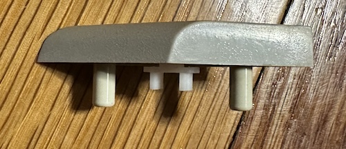
Notice the long plastic legs on the keys. These help stabilize the diagonal overhanging portions of the keys, and are the reason for the holes in the 3D-printed option key plate above.

The adapters are fine, though I will admit they seem a little tall, and the keys are a little wobbly. They might be able to be finessed a bit with a file to make things the right height and line up, and I may try that later.
Finished!
Make sure to install the spacers, and screw everything together; when not fully put together the board felt a bit too easily flexed and I was worried about the rear of it hitting the shield on the side, but with it all attached it feels much more stable.
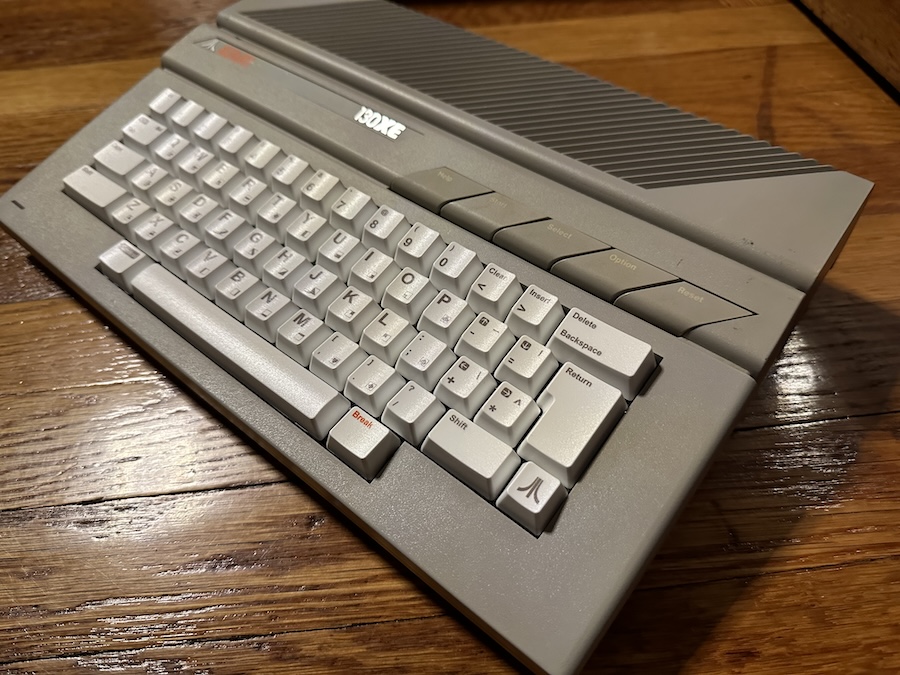
It’s a real good-looking keyboard, even if the labels having the symbols on top rather than on the front side might remind you of the Commodore 128 or some models of 64C. If that happens, I recommend booting up the audio test and seeing the fourth voice, reminding you that this does still have a POKEY. Phew.
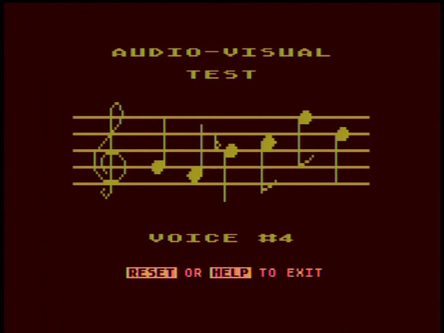
And how does it feel? Worlds better!
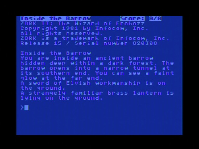
And now, finally, I can play Atari today. Though, while the keyboard now makes it great for text adventures, I think I need to get myself an S-Video cable: the Atari text mode has a great font, but it’s not the easiest to read over composite capture. (It’s actually a single-color mode that can only vary in luminance)
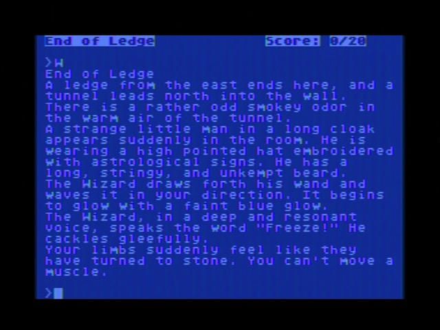
…also, fucking Wizard.
