Is the Twin Famicom Flawed? The Case of Guardic Gaiden
So recently I’ve been binge-watching RandomStranger’s Famidaily project and came across his video on Guardic Gaiden, the game we know in the west as The Guardian Legend. In it, he said that the Twin Famicom has slowdown on this game that the regular model doesn’t. Now, I’ve been a big fan of the Sharp Twin Famicom– it’s got no lockout chip, a built-in Disk System, standard AV output, and the Famicom microphone, so it has a lot going for it. But is it true that this “hidden gem” is it’s “Achilles’ heel”?
Undone by UNROM

Both Guardic Gaiden and The Guardian Legend use the same mapper: Nintendo’s UNROM. UNROM is one of the most common mappers for the console, as well as one of the simpler ones, used on titles like Castlevania, DuckTales, and Rygar. (The infamous contract developer Micronics also liked it a lot, using it in titles like Super Pitfall, Athena, Ikari Warriors, 1942, Ghosts ‘n’ Goblins, and more, but we won’t hold that against it) Here’s another example, Konami’s Rush ‘n’ Attack:
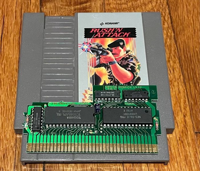
UNROM is a “discrete logic” mapper, made of just two widely made and available logic chips (a 74161 timer acting as a latch, and a 7432 OR gate used to create a fixed bank). It always used CHR-RAM on the video side, and has a fixed program bank and a mappable one. For more information on NES mappers, I already wrote a long post on that, so check it out. It’s still used by homebrew developers as a cheap option when fancy features aren’t required.
What are those fancy features that are missing?
- No nametable mirroring control. The Famicom’s two nametables can be horizontal or vertically arranged, but with UNROM you can’t control them during the game. MMC1 game Metroid uses that mapper’s capability for its different scrolling directions, as an example.
- No expansion audio. The NES couldn’t do this anyway, but the Famicom allowed the cartridge to mix in additional music or sound effects.
- The mapper has a risk of bus conflicts between the ROM and the CPU, so you have to be a bit careful when changing the program banks.
- No additional work RAM, battery-backed or otherwise. UNROM games pretty much have to have passwords if the developers want to let you restart your progress. (Presumably homebrew variants can do what they want.)
- No cartridge IRQ.
The last one is the relevant one here. The IRQ line on MMC3, for example, allowed for Super Mario Bros. 3 to have its bottom-of-the-screen status bar, by signaling to the console’s CPU that a certain number of scanlines had been drawn on-screen. Unlike the Master System, the stock NES doesn’t offer any way to tell what line the console is currently drawing, so cartridge IRQs are useful for when you want to do screen splits or other “raster” effects.
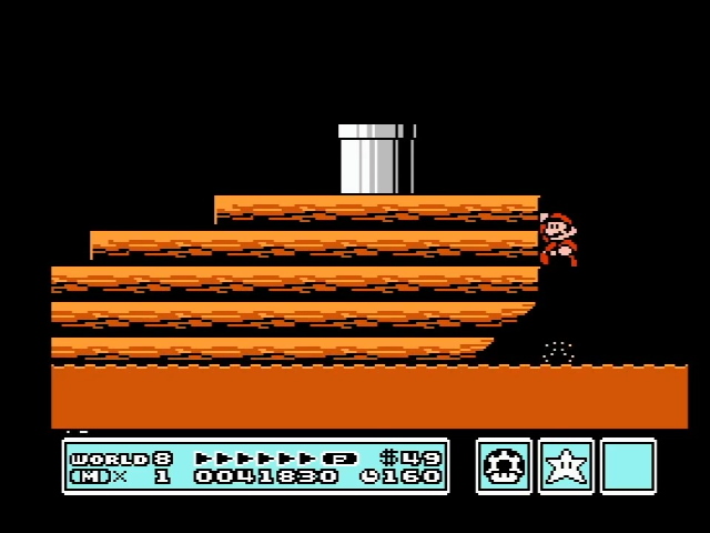
Without an IRQ, the only way the NES offers to split the screen is the “Sprite 0 hit”. Essentially, when a non-transparent pixel of the first sprite interacts with a non-transparent pixel of the background, a flag will be set inside the PPU. You can read that flag, but it won’t interrupt– you just have to sit there over and over checking for the flag to change. This of course precludes the CPU from doing things like running game code, so when you see screen-splits in UNROM games like Castlevania, they’re usually at the top of the screen; that way, game code can still run during the majority of the screen below the split.
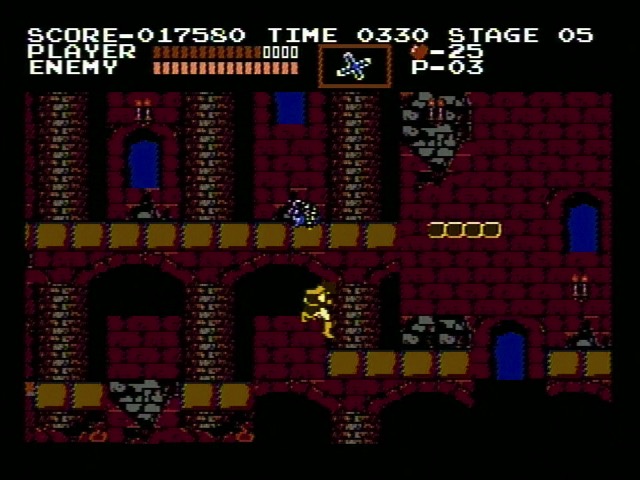
And we can see the same in Guardic Gaiden, its fixed status bar is of course at the top…
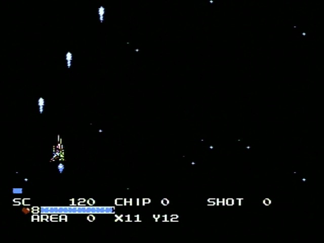
Oh right, this is a Compile game. And Compile, much like Rare, were very good at the whole “squeezing every last bit of performance out of 8-bit consoles” thing.
No cartridge IRQ…
When an IRQ interrupt occurs, the 6502 processor always fetches the two bytes at memory address 0xFFFE. (NMI, used for vblank on the NES, is at 0xFFFA, and at reset it fetches from 0xFFFC. This is called the “vector table”) So if you take a look at a game, you can always find the IRQ from looking at those bytes. Well, sort of– memory mappers do complicate this a bit. But emulators like FCEUX will let you see the memory map that the CPU sees at any given moment.
In my basic NROM-128 game Aspect Star N, there is an IRQ handler, but it’s just a single RTI– the 6502 call for ending an interrupt and returning back to the main code. I don’t think it will ever be called, but it’s good to have as a matter of course. Take a look at Castlevania, and you’ll see that they did something more clever: the interrupt vector points to an RTI, but it’s the same RTI that ends the NMI handler. Every byte counts.
Here’s a video I’ve made of Guardic Gaiden, modified so that, much like Castlevania, its IRQ now points to the RTI at the end of the NMI handler. And it’s pretty broken! Especially in that screen split. So now we’re getting somewhere.
IRQ where are you?
Take a look at the Famicom schematics, and you’ll see that nothing is attached to the IRQ line, though it does connect to both the cartridge port and the expansion controller port. But that doesn’t mean the IRQ handler will never run.
For this, I’ll hop into the FCEUX emulator, and use its debugger to set a breakpoint at the IRQ handler, 0xDCF3. This is pretty similar to the debugging you’d do when developing an NES game, so I’ve gotten plenty of practice lately. The interrupt doesn’t fire on every frame, but here’s the first interrupt I hit, after getting hit by an asteroid on the first stage like immediately. For someone who writes a lot of words about video games, I really could do to get better at playing them.
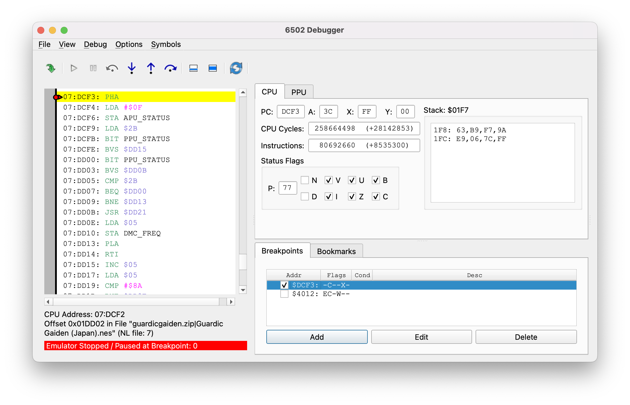
There’s a lot going on here! On the left column we can see the internal disassembly of the function. I’ll annotate it a bit.
07:DCF3: PHA            ; push the accumulator on the stack so we can alter it
07:DCF4: LDA #$0F
07:DCF6: STA APU_STATUS ; Write to the audio status register
07:DCF9: LDA $2B
07:DCFB: BIT PPU_STATUS ; Check the PPU status register
07:DCFE: BVS $DD15      ; The "V" flag will be the Sprite 0 hit
                        ; If it's already set we might have missed it, so
                        ; it jumps to a different routine
07:DD00: BIT PPU_STATUS ; Now we keep checking in a loop
07:DD03: BVS $DD0B      ; If it's hit jump to 0xDD0B
07:DD05: CMP $2B        ; Sprite zero has not been hit, look at memory
                        ; address 0x002B
07:DD07: BEQ $DD00      ; Loop back to DD00 if its 0 and check again
07:DD09: BNE $DD13      ; Just jump down and leave the interrupt if it's not
07:DD0B: JSR $DD21      ; Sprite zero has been hit, so jump to a routine
                        ; to split the screen
07:DD0E: LDA $05
07:DD10: STA DMC_FREQ   ; Change the frequency of DPCM
07:DD13: PLA            ; Put the accumulator back to where it was
07:DD14: RTI            ; Leave
The main thing going on here is that we’ve double-confirmed that the IRQ is part of the screen split. And Guardic Gaiden is indeed using sprite 0 for that, but they’re also using an IRQ to go to the checking code. Presumably the sprite 0 hit is being used for more exact timing than whatever this IRQ method can provide.
And where did the IRQ come from? Well, looking at the disassembly it seems to be doing a lot of messing with the audio registers, which is suspicious. But ignore that. Because if you see the “Status Flags” section of the debugger window, you’ll see that the “B” is checked. What’s the B flag? Well it’s not a real flag, but the details aren’t that important. What matters is, the B flag being checked means that this interrupt was triggered by a BRK.
BRK is just an opcode of the 6502. It’s opcode 0x00, so it can be useful for debugging; it triggers an “artificial” interrupt. In this case, Guardic Gaiden appears to be using a BRK to break out of the logic it’s running and just wait for the screen split point to continue. Any 6502 program can do this; a break is generally slower than a JMP or JSR.
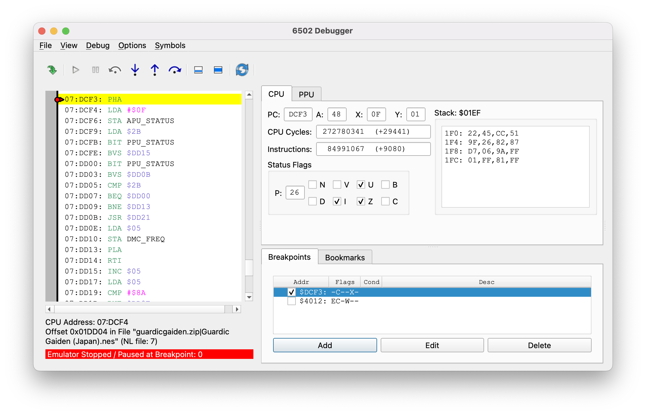
But skip ahead a few times and there are some interrupts that don’t have the “B” flag set. They go to the same IRQ handler, and the code doesn’t check for the “B” flag. So what’s the deal?
The DMC DMA trick
The TCRF page on The Guardian Legend links to a Japanese Twitter thread accumulator where the actual developer who worked on the game, Twitter user @kopandacco, speaks a bit about their experience making the game, and dealing with the Famicom’s limitations. Including a clever trick to get around the lack of interrupts.
ファミコンにはサンプリング音源が積んである。制限が多いので当時は全然利用する気がなかったんだけど、この音源はデータ再生終了時に割り込みが発生可能になっていた。- @kopandacco, 4/16/2014
“The Famicom has a sampling audio source. Because of all its restrictions I didn’t want to use it at all, but when it was done reading data it was possible for that sound source to trigger an interrupt.”
That’s why the interrupt handler above messes with the DPCM registers. Guardic Gaiden doesn’t use DPCM for audio, but it uses it to trigger an interrupt a certain amount of time into the screen. The NESdev Wiki mentions the technique, but attributes it to a forum thread from 2010. Here’s Guardic Gaiden doing the same thing in 1988!
But later in the thread we now see the Twin Famicom referenced.
実際うまくいった様に見えたんだが・・・リリース後、一部のファミコン(ツインファミコンだけ?)で激しい処理落ちが起きるようになった。なんでかというと、一部の本体ではDMA終了割り込みが起きないのですよ先生 - @kopandacco, 4/16/2014
While it looked fine to me, after release, one category of Famicoms (only Twin Famicoms?) started to show severe processing delays. It seems that some consoles don’t have DMA interrupts.
As far as I can tell, this is the source of the claims that Twin Famicoms have slowdown when playing Guardic Gaiden. And it’s a pretty good source!
Not all Twins
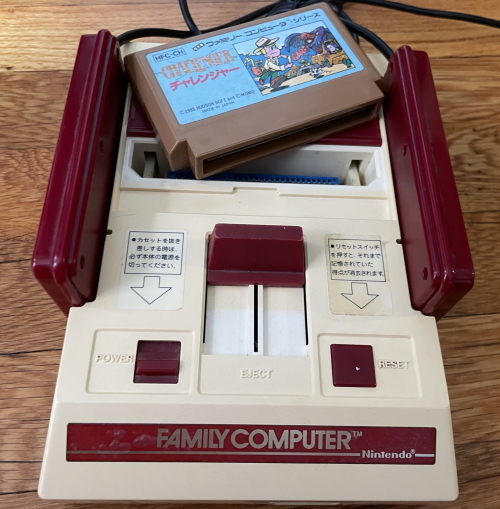
I have two Twin Famicoms. They’re not even twins, since one is the later model with built-in turbo controllers. That’s the black and green one on the left.
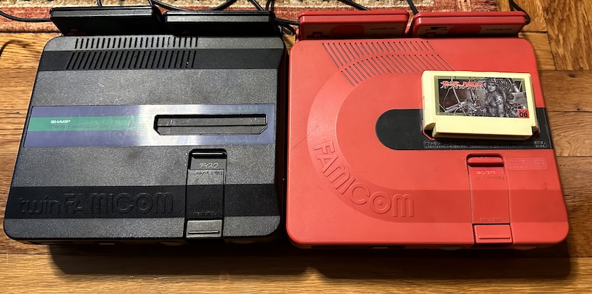
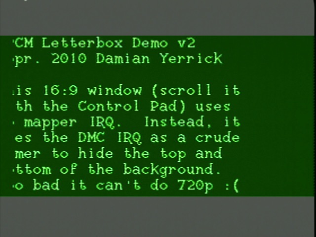
And neither of them shows any slowdown on Guardic Gaiden. And I’ve tested a number of methods. I switched to a DPCM hardware test ROM intended for emulator authors, and still, no issues on any model, including burned to an NROM cartridge (a leftover from Aspect Star “N”’s limited run). See, I started to think that maybe the IRQ line had a potential issue, and an Everdrive has its own IRQ circuit that could be getting in the way.
Now, @kopandacco’s tweet outright says that it wasn’t all systems that showed the issue. And I do have a theory here for what may be causing it. See, the Ricoh 2A03 is a bit of an odd-ball. Take a look at the die shots on Visual 6502. See that big block in the bottom right? That the 6502 die. Chip dies like this weren’t protected in the United States until 1984 (I couldn’t find any equivalent dates in Japan); the only protection companies like MOS (by 1983 a Commodore subsidiary) had was patents. And the 2A03 infamously lacks the patented decimal mode. There is an internal connection between the IRQ line and the DMA unit used by the DPCM audio channel.
Resistance is futile
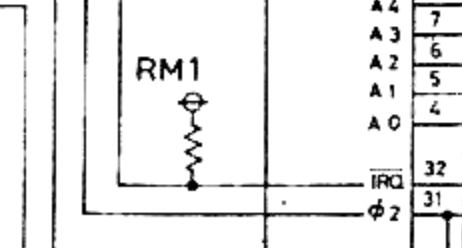
Here’s a bit from that Famicom schematic earlier. Notice there’s a resistor pulling the 2A03’s IRQ line high. The way the IRQ line works is that an interrupt fires when it’s low, and will continue to fire until it goes high again. This is why you need to “acknowledge” interrupts; this is why Guardic Gaiden writes to APU_STATUS above, to acknowledge the DPCM interrupt.
The value of that interrupt isn’t listed on Nintendo’s schematic, but Enri’s lists it as a 10kΩ resistor. That’s pretty typical for a pull-up resistor. Connecting it directly to 5V would mean that anything that wanted to fire an interrupt would have to short-circuit the power supply. Realistically, nothing you’d attach to the bus would be capable of handling that current and it’d just die or fail to interrupt.
Despite its mods, my Nintendo Famicom has nothing changed on the IRQ line, and with a multimeter I can measure that 10kΩ resistor. But on my Twin Famicoms, it’s more like 220Ω. Why is that? Well, I needed to crack open the newer Twin anyway because I put it together wrong last time I opened it. (the red one gets a lot more use despite the lack of turbo buttons)
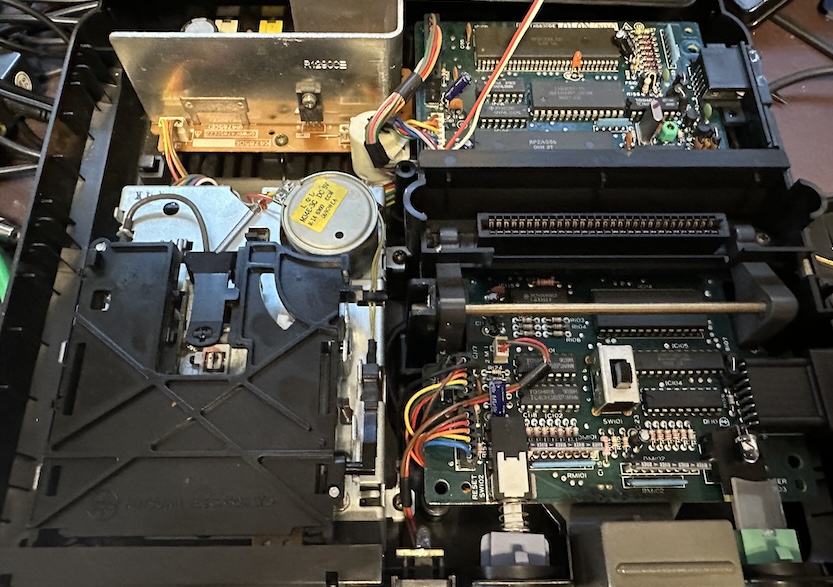
So I think I narrowed down the pull-up to these resistors here; specifically I think it’s R149.
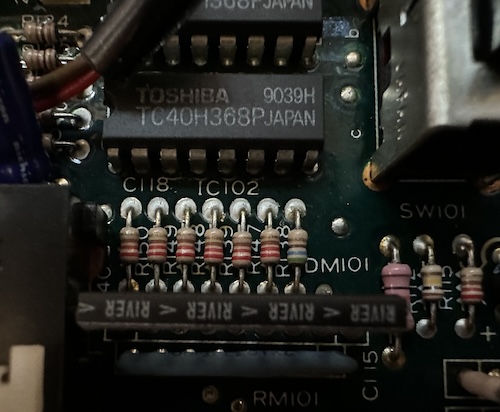
I’m not great at the color code, but I believe those are indeed 220Ω resistors. I’m not sure why they used a lower resistance here than on the standard Famicom, but I could see it plausibly that more marginal 2A03 chips could be unable to overcome the pullup. (Remember, a weaker pullup resistor means more current pulling up the voltage) As @kopandacco notes, Nintendo wasn’t testing parts for the DPCM IRQ, as it hadn’t been used by commercial games up until that point. If this is the problem, though, Sharp never updated their design to accommodate it, as this is my later model console.
I guess I’d need to find a Twin Famicom that exhibits the bug, and see if replacing the pull-up resistor with a larger one fixes the bug. Might be worth an experiment? But at least for my Twin Famicom, it still sits atop the Famicom hierarchy.
Recreating the bug
Let’s take a look at the above IRQ handler to see if we can recreate the bug’s impact.
07:DCF3: PHA            ; push the accumulator on the stack so we can alter it
07:DCF4: LDA #$0F
07:DCF6: STA APU_STATUS ; Write to the audio status register
07:DCF9: LDA $2B
07:DCFB: BIT PPU_STATUS ; Check the PPU status register
07:DCFE: BVS $DD15      ; The "V" flag will be the Sprite 0 hit
                        ; If it's already set we might have missed it, so
                        ; it jumps to a different routine
07:DD00: BIT PPU_STATUS ; Now we keep checking in a loop
07:DD03: BVS $DD0B      ; If it's hit jump to 0xDD0B
07:DD05: CMP $2B        ; Sprite zero has not been hit, look at memory
                        ; address 0x002B
Why is there a special handler (0xDD15) for the first hit? Because it assumes in that case, we’ve missed the sprite zero hit, and need to restrict how many actions are processed per frame so that we don’t miss it again.
If you change the second BVS to point to the same address, you can create a variant of the game where it assumes every single call took too much time, even those triggered by a BRK. This flickers the status bar, but also does start to slow down even before the first stage completes. You can do this by changing the byte at 0x1DD14 in a standard-format ROM dump to 0x10. (Remember, branches are relative)
An Aside
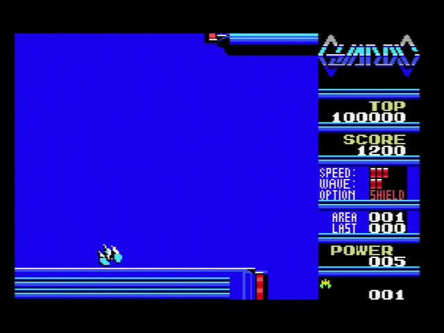
The existence of Guardic Gaiden implies the existence of regular, non-Gaiden Guardic. And so it does exist: it’s a 1986 MSX game, running here on my Panasonic FS-A1F MSX2 in RGB. (Very nice after all these composite Famicom shots!) Note that while I’m running on an MSX2, this is an MSX1 game, and limited to a 32kiB ROM; on the Famicom Compile had 128kiB, a full megabit, to work with.
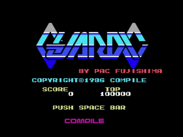
The game is a series of single-screen shoot ‘em up rooms, with quite aggressive enemies. If you’re experienced with the MSX at all, you probably know that scrolling wasn’t exactly the console’s forté. Or even its Rockman.
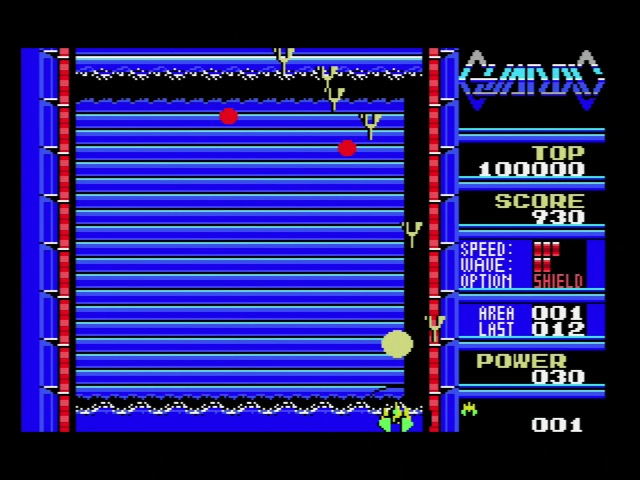
The shooting rooms are connected by hallways that lead to more shooting areas. It’s easy to see how Guardic Gaiden took the concepts of Guardic and evolved them into a game more suited for the scrolling-capable Famicom hardware and the action-oriented console market. Very nice!
