Composite Mod on the CoCo 2: The UVD Board
Since at least March of 2019, the Tandy Color Computer 2 has sat there, teasing me. It has a Motorola 6847, the tragically disappointing graphics chip, paired with the terrifyingly powerful Motorola 6809 CPU (running at… substantially less than a megahertz, but we all have our flaws). Truly a machine that should provoke more interest from me than it does… except for the fact that it only has RF output. Let’s finally fix that.
The Tandy Color Computer
The TRS-80 Color Computer and Tandy Color Computer 2 are pretty much the same computer; the Color Computer 2 is a cost-reduced variant with a better keyboard and more RAM. Also, at least mine is branded “Tandy Color Computer” rather than “TRS-80 Color Computer”, which is good, because despite Tandy Corporation’s fondness for the TRS-80 acronym, the 80 did originally stand for Z80, and there’s no Z80 anywhere here.
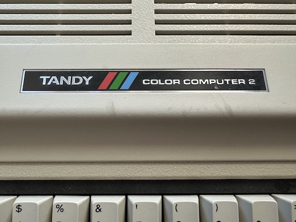
Well… there is one other big difference. If you search the internet for a Color Computer video mod, you’ll find a ton, but just like this page on CoCopedia, they’ll pretty much only talk about the original model.
So, why do they only include the original Color Computer? Because of how the Motorola 6847 works. You see, unlike some other chips you might be more familiar with, like the NES PPU, the 6847 doesn’t actually have a composite output pin. Instead, it outputs a few signals, that are kind of like component but are not quite, since they predate the component video standard by quite a bit. A second chip, the MC1372, handles modulator output and combining the signals, as you can see in this block diagram excerpt from the 6847 datasheet.

I assume this was probably in part to offset the complexities of different television standards; it looks like that the Welsh Dragon 32 computer uses what appears to be an LM1889 instead of the MC1372. But in any case, the MC1372 is where pretty much every CoCo 1 composite mod gets its video output.
Here’s the problem, then. Look at the circuitboard of my Color Computer 2. The large Motorola chip labeled XC80652P is the Motorola 6847. (Actually, it seems to be a 6847T1, which adds advanced features like ‘lowercase letters’. The CoCo ROM was never upgraded for this, but it might be worth poking at in the future.) But none of those small chips are the MC1372.
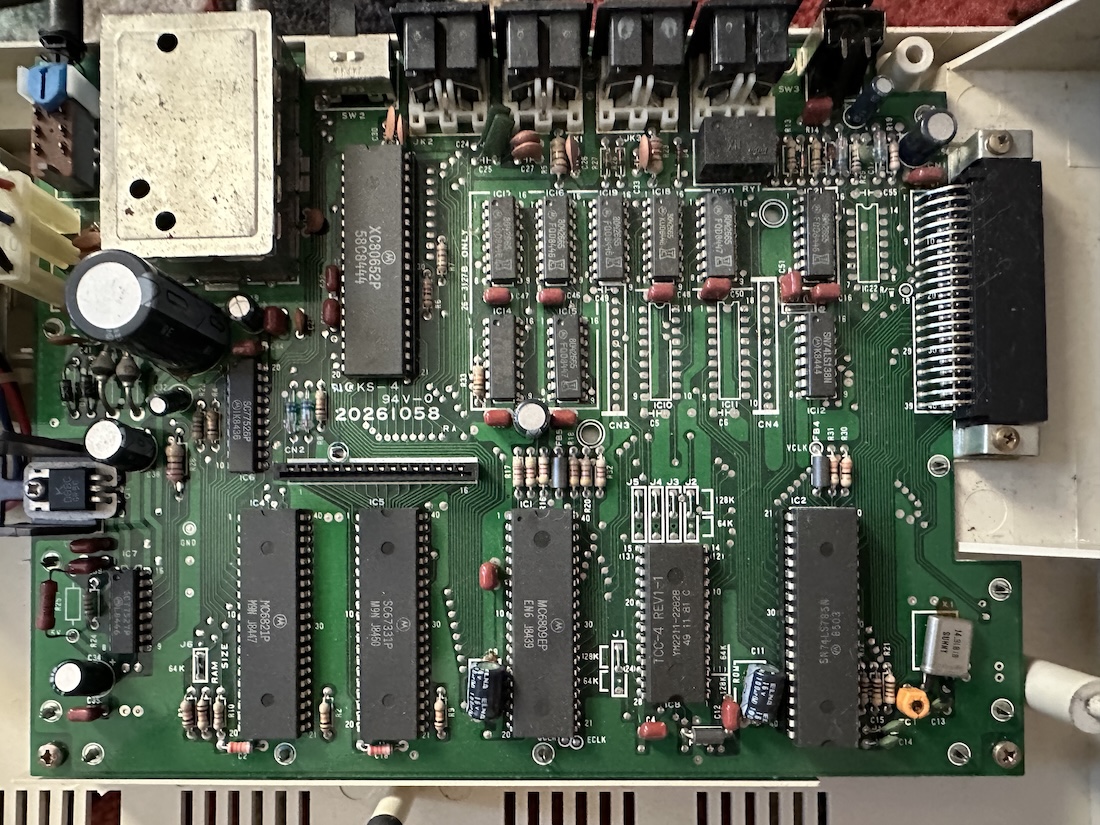
Instead, those somewhat-component video signals appear to go directly from the 6847 to the RF modulator, which then just directly outputs RF. So it appears I am doomed to have my Tandy’s video output look like this:

Or am I?
Kits galore
So there I am, searching the electronic auction house, trying to avoid sellers outside of my country as we’ve suddenly put in place an aggressive import tariff regime. So no more Japanese hardware for me, it’s time to focus on stuff from the good ‘ol U. S. of A.
Specifically, I found this listing (how long will this link stay good? who knows), which advertises a clone of the Mark Data Products Universal Video Driver (“UVD”), a period composite video mod, which promises two interesting features:
- It’s solderless, and you just clip onto pins
- It promises to support the Color Computer 2
I am notoriously terrible with a soldering iron, and have a Color Computer 2. So let’s see how this goes!
By the way, I should note, I have no connection whatsoever to this eBay seller. I have never spoken to them, most certainly received no compensation for this post, and did not give them any ability to review this post beforehand.

The UVD circuit is fairly straightforward, being all discrete transistors, capacitors, and resistors, attached to basic clip leads, with output as RCA tails. One thing that’s worth noting about the UVD is that it doesn’t follow the basic CoCo 1 circuits above; instead, there are five clip leads: separate luminance and chrominance, audio, with +5V for power and ground for ground. Note that the Motorola 6847 does not output chroma either; for that, you’d still need the MC1372.
Secret of the RF Modulator
So let’s take a look at the manual for the original, which the remake kit also uses. My late model Korean-made Color Computer is in the last page of this document, so it’s probably the last model released.
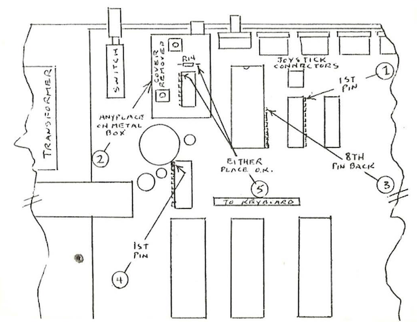
This is a bit of a mess, because the points are numbered, but on the board itself they are only distinguished by color. I suspect this is not the fault of the recreation kit developer; the numbers are correlated to colors in the original manual as well.
- Red - +5V, Power
- Silver, Ground (the clip provided is more blue but on a silver wire)
- Yellow, Luminance
- Black, Audio
- Green, Chroma
So for the chroma, it recommends pulling it from a chip inside the RF modulator; it seems that now we can no longer simply treat it as a black box. And this is a bit of a shaggy dog story; after all that time telling you the Color Computer 2 is harder to AV mod because of the lack of an MC1372, what do we find inside the box?
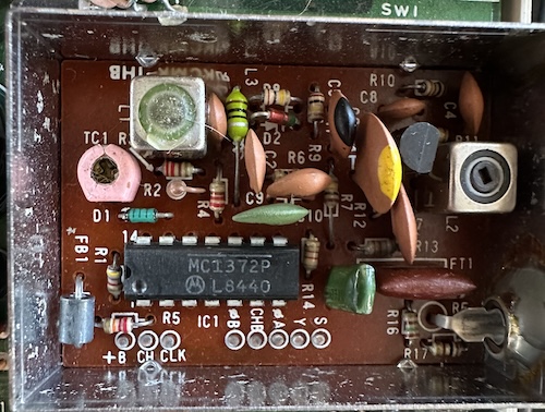
That’s right; of course, the core of the Color Computer 2’s RF modulator is none other than the Motorola MC1372 chip. Could it be any other way? And the lid is extremely easy to remove, at least in my case it wasn’t soldered or even crimped on that tightly. At any point, had I realized it, I could’ve at least tried nearly any of the CoCo mods out there that relied on the MC1372. (And this documentation has been freely available for decades, so I have little excuse!)
Unlimited power, from somewhere
But no matter what I could’ve done in the past, we’ve got the fancy kit now, so let’s hook everything up using that.

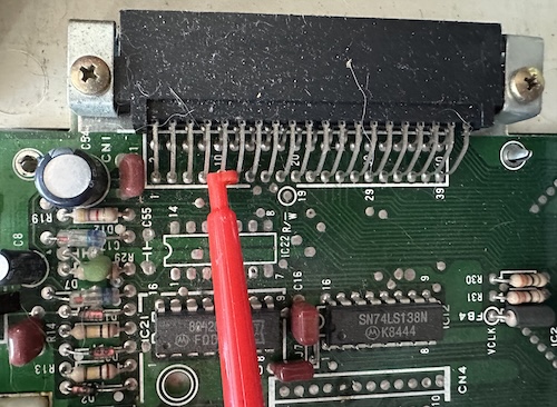
My work ended up a bit chaotic, but I will say the guide is perfect. Well, almost perfect. I didn’t really get a good power connection using the point they recommended; instead, I snagged +5V from pin 9 of the cartridge slot. This was a lot easier to grab onto with the clip lead, and so far hasn’t caused any issues with use of cartridges.
Give me video
And now that we’ve hooked everything up, what do we see?
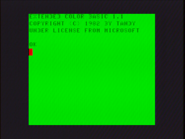
Well, it’s not the best thing I’ve ever seen. But it’s a Motorola 6847; and as usual for them, it does look a lot better on my CRT than over this capture setup. (Which started having some weird issues, actually) And it’s certainly worlds more convenient than that RF box was.
But I will warn of one particular issue I had; after closing up the system, things seemed to work alright over a CRT still, but when I took a screenshot to show some text behaviors, I got this picture.
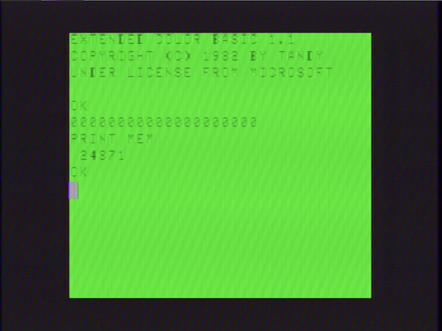
The text is a lot less readable; either a luminance issue or a chrominance one. Either way, I suspect it’s because a connection got bashed when I closed things together, probably too aggressively. The best way to solve this? Solder the connections, of course. Which I might just do, now that I know this works with clips, but for now I just bent the clips a little more aggressively to make better contact.
Why was I trying to take this picture? Well, two reasons:
PRINT MEMreturns 24871. This is because it matches the 32kiB Color Computer 1; the additional RAM is hidden behind bankswitching, and Tandy never updated the BASIC ROMs.- The
0has a line through it. This confirms that this is the upgraded Motorola 6847T1, so it should be possible to show lowercase text– of course, Tandy never updated the BASIC ROMs for that either.
With this kit, my Tandy Color Computer should become a lot more usable, and this system definitely has a lot of quirks to explore. So I’m looking forward to it!
