Throw it in the box: The Sega Master System II Power Base RGB!
A smaller one since a larger project kind of flopped and I don’t want to think about it right now, so it’s a system we’ve seen before here: my French Master System II, seen in Alf 2 and the Mark III rundown. What makes this Master System unlike other ones? Do you actually need a special cable? Why does Nicole find this interesting? All of these questions except the last one will be answered!
The Master System II: It’s back
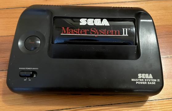
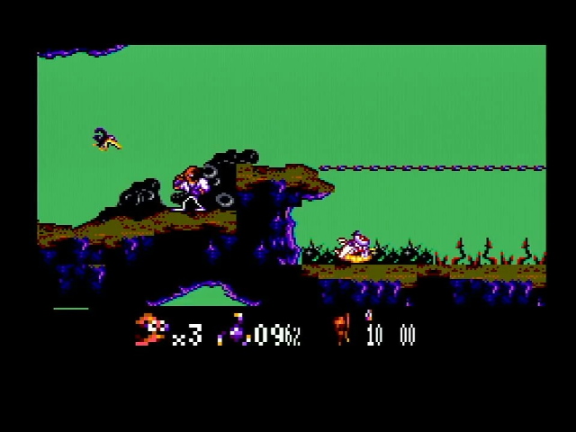
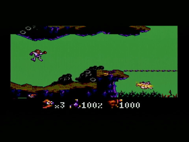
Quick overview: The Master System II was released in 1990 (only in Europe and the Americas, as Sega had given up on the console in Asia by then), a redesign of the Sega Master System to make it cheaper to manufacture. The console wasn’t just a price drop, though; it features an improved VDP (Video Display Processor) with additional graphics modes and some bugfixes in features like scaling, as can be seen in the Brazil-only Earthworm Jim. First screenshot is a Japanese Master System 1, second a Master System 2.
This is all well and good. But a major problem with the Master System II was that it was, in the end, a cheaper model. Not only did it get rid of the reset button and the card slot, it also got rid of the AV output the Master System featured. No RGB output is available on these systems, not even composite. Without modding your system, you’ll be stuck with RF. Most people in 1990 would find that perfectly normal; enthusiasts in 2021, though, might not be so happy.
You did have one other option, though: move to France.
Or Switzerland, I guess
When it comes to RGB video, France is pretty much the promised land. The country originated the SECAM color video standard, which had two major traits that made it stand out from NTSC and PAL composite video.
- It used frequency-modulation to encode color data. This improved fidelity (though at the cost of half the color resolution), but also meant that you can’t overlay SECAM video signals on top of each other. Video editing would need to be done in some other form, whereas NTSC and PAL use amplitude-modulated systems that can be summed more easily. This generally meant video professionals in France have to work either in PAL or in component-style video.
- It isn’t PAL.
The second meant France had to be catered to anyway, and the first meant that the French video industry was more used to working across video standards. It’s no wonder that France is the source of the SCART connector; as you’d expect for the Syndicat des Constructeurs d’Appareils Radiorécepteurs et Téléviseurs. The SCART connector, bulky though it may be, is still the most common connector even among hobbyists for 15kHz RGB video; the original standard dictates using a composite video as the sync signal. Sync as a concept is a nightmare, but in short, a PAL composite signal could be used to provide sync for a French RGBS TV, and a PAL fallback for the rest of Europe, where RGB SCART was slower to adoption. (Sync pulses only depend on video timing, not on color encoding)
What that meant is that by 1990, while RF-encoded composite was probably fine for the low-end market in countries like Germany, Brazil, and the United States, it seems to have not been enough for France. Even if they had an RF-modulated SECAM variant, the hassle of an RF switch would definitely make them look very old-fashioned in a market where even low-end TVs were now sporting SCART ports. (By comparison, here in the US I recall low-end TVs were often RF-only nearly all the way up until the end of the CRT era)
Let’s crack this baby open
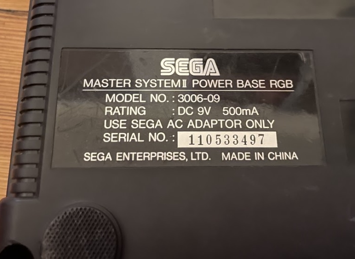
Looking on the back, we see the top is held on with just five screws, and that the system is labeled the “POWER BASE RGB”. It seems that at least in labels on the back, the “Power Base” branding still managed to linger on well into the Master System II era. Remove the screws and a metal RF shield, and we see the circuitboard. Ignore the tricolore wires; they were for a region mod.
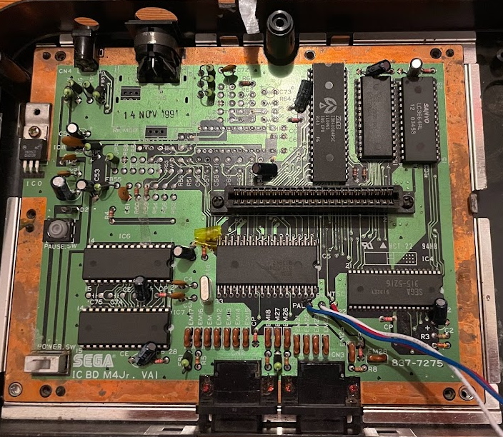
And why is this board, Sega part number 837-7275, so easily region-modded? (It literally is just removing one jumper and adding a switch where I have wires attached) And why are there so many unpopulated parts? Well, I don’t have a lot of Masters System to compare, but I do have an internet connection, where I can see that SMS Power has a scan of the American Master System 2 board. The same revision! And the PAL circuitboard is completely different, so we know that this isn’t just a coincidence.
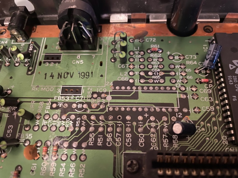
IC9 is the interesting one. You see, on the US Master System II, this is populated by a Sony CXA1145P. This is a video encoder; it takes the raw RGB signals off of the VDP (the large 64-pin chip with the alternating pin lengths) and outputs amplified composite video. It also outputs amplified RGB and S-Video signals, but presumably it’s only the composite that gets used on the US Master System 2, being fed into the RF modulator box. (You can also see that they left room to use multiple different modulator footprints)
So this board has no video amplifier. You can confirm that with a multimeter. Touch pin 6 of the multi-out (CN5), which outputs the red signal, and then touch pin 27 on the VDP with the other lead. If your multimeter’s in continuity mode, the multimeter should beep. If it doesn’t, you might want to resolder CN5, as solder connections on connectors like this can easily crack.
Why do you need an amplifier?
So, there is no amplifier chip. This has some interesting implications. First, you can’t use a standard SCART cable from the time. Remember, those were designed to use a composite (either PAL or SECAM) signal as sync. This can’t output anything on the composite video pin. It can on the TTL CSYNC pin, but that signal needs special treatment before you can shove it somewhere expecting composite video.
Still, if you have such a CSYNC cable, you might think that you can just plug it in. Au contraire, mon fraire! Like all Master Systems 2, this console contains a built-in game; in this case, it’s Alex Kidd in Miracle World. How does it look using a Sega Genesis 1 CSYNC cable?
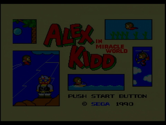
It is quite dark! And this cable works without issue on a standard US Master System 1. It works there, because that console does include a video amplifier chip. The signals coming off of the VDP are simply not designed to be directly shoved into your TV. If you’re looking to use a term from an analog electronics class, the word is “impedance”. Video inputs, like the Micomsoft Framemeister that upscaled that image, generally expect a 75Ω impedance. However, electronics like the VDP usually do not have enough power to drive that; without amplification, you see what’s above.
So what we see in the French Master System II is a compromise: the circuitboard from an NTSC console, with a video bypass. This makes me wonder why exactly the PAL circuitboard is different; it looks like this is to accomodate the 315-5217 IO chip, which has more pins. Nevertheless, I’m not sure why this different IO chip was needed, and what those additional pins do. (SMS Power claims that the 5217 IO Controller is used in both NTSC and PAL Master System IIs, but this doesn’t match their scans)
But surely they couldn’t have just expected French users to massively crank up the brightness on their TVs, right?
The power’s in the cable
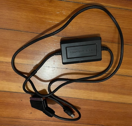
This is the SCART cable designed to go with the Master System II Power Base RGB. The cable feels very nice to the hand, but that’s not very relevant. What is relevant is that you might notice that it’s not just a cable; there’s a SCART head at one side, and a DIN plug on the other side, but there’s a box in between. What does it say on the box?
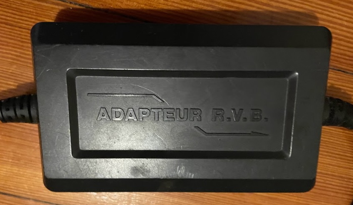
Ah! Above I called France the promised land of RGB, but you see here that I should’ve called it the promised land of RVB: rouge, vert, bleu. This separate box is what contains our amplifier. It’s a bit surprising to me that this was cheaper than including an amplifier chip on the board, but then I opened it up. Inside is an adorable single-sided circuit board.
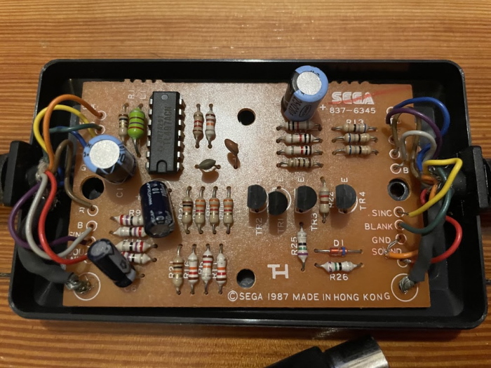
The board is mostly analog components. It has been diagrammed by SMS Power so I won’t go through, but unlike the American and Japanese Master System 1, the RGB video signal is amplified using simple single-transistor amplifiers rather than a dedicated chip; perhaps those CXA1145Ps really were too expensive to use in a case where you didn’t need the composite video.
The lone IC is a TL497ACN, from TI. This is a step-up voltage regulator; this seems to be used to provide the 12V which the SCART standard requires as a signaling voltage. Fun fact: most hobbyist/enthusiast “SCART” cables leave this pin disconnected, which means they may not work on SCART TVs.
One thing that surprises me is the 1987 copyright date. Was Sega using this cable with European consoles during the Master System 1 era? I only have US and Japanese Master System 1s, and while their signals are different from each other, neither requires additional amplification of the RGB signal as far as I know, and both have video amplifiers on-board. However, looking at SMS Power again, they do have what looks like an RGB-only Master System 1. On the board, you can see the video signals are jumpered with bodge wires on an NTSC motherboard.
In any case, with the Adapteur RVB, we get a much more tolerant signal on the Framemeister:
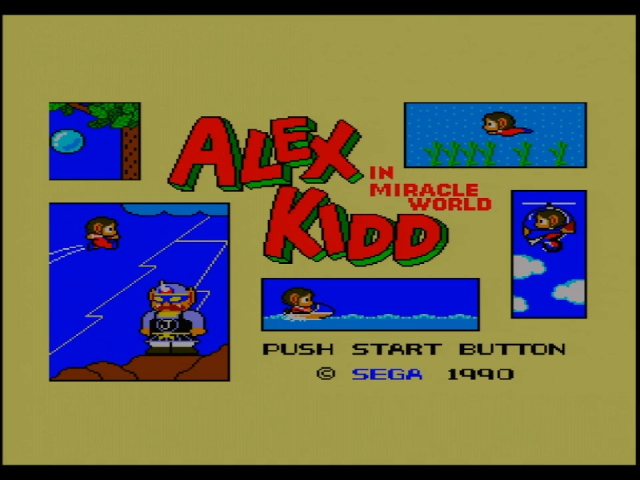
The colors might be a little dark still, but this is definitely within the range where one can ebe expected to adjust the brightness. (And indeed, it looked better with the RetroTINK-5X in the living room than with the Framemeister on the capture setup)
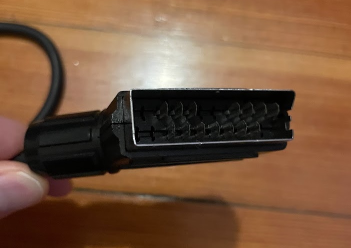
One other thing I noticed is that the Adapteur R.V.B.’s SCART head is missing pins. This is pretty normal for mass-produced cables; at a certain point, the extra cost of the metal for the extra pins you’re not going to use will be higher than the cost of getting special parts custom-made for your application.
Troubles in paradise
Oddly, I couldn’t get this cable to sync at all with the OSSC, despite working well with the RetroTINK-5X and the Micomsoft Framemeister. The OSSC is usually one of my most reliable systems, and still sits at the core of my living room setup, so what gives? Using even a gscartsw with two powered outputs, one going to the OSSC and one to the RetroTINK-5X, it works on one and not the other.
It’s worth noting that this isn’t an issue with the Master System II; in the past you’ve actually seen shots from it using the OSSC, but in that case, I was using an HD Retrovision cable with an adapter. As you can see from the comparison shot (both on the RetroTINK-5X, of course), with the component cable first, the signal is again a bit too dark with the HD Retrovision cable. This can be adjusted, but is likely just because of how those cables are designed to be quite flexible and accomodate a large amount of consoles, not just this one.
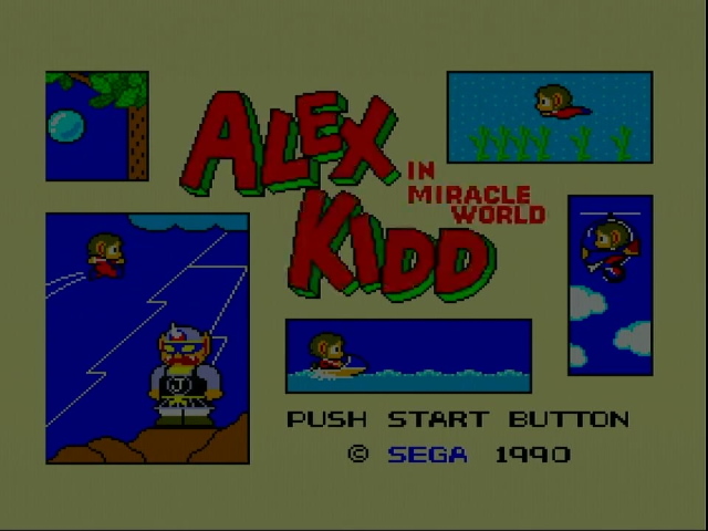
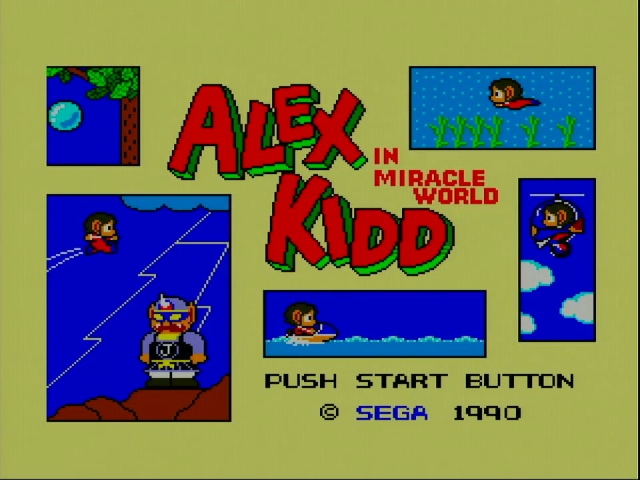
In any case, this is an odd corner of:
- Obscure SEGA nonsense
- Video signals
So I guess it was inevitable that I’d find it interesting. I hope you do too! Once I get better with an oscilloscope (and also probably a better oscilloscope), I might take a look at the sync signal to see what’s going on with the OSSC. Until then, though, I think this is about all this topic gets.
Update 1/22/2022
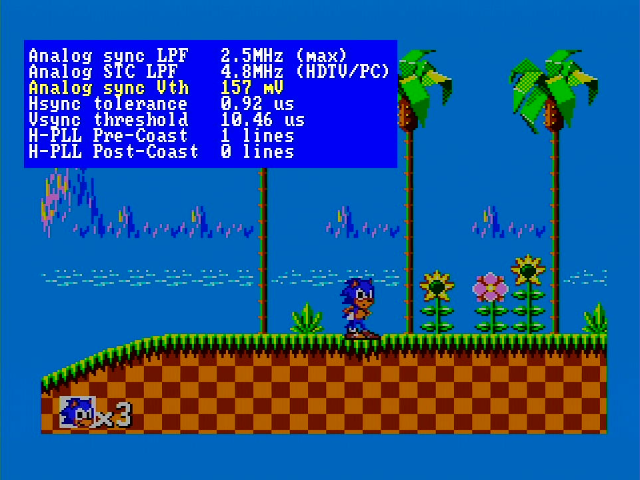
It looks like there is a way to use the Adapteur R.V.B. on the OSSC. I saw this thread which reports that all that’s necessary is an adjustment of Analog sync Vth, which is the sync slicer threshold. A nice thing about the OSSC is how endlessly flexible it is. I took a quick screenshot and confirmed that this does work for me, though I had to increase it a notable bit for the picture to be stable, and I’m not sure what impact this might have on other consoles. Probably best to create a preset just for this one.
