Composite Video: Why it was good then, and why you might even use it today!
I’ve been talking about video a lot lately; but that was all arcade or some other RGB upscaling. But let’s face it: if you grew up in North America, your arcade may have used RGB monitors, but you almost certainly didn’t have that at home. If you were like me, your video games came over a single yellow wire. (plus audio) But today, you probably want more wires. Why? And what was going down that wire?
What is composite video?
When we talked about interlacing, I mentioned that a monochrome video signal has near-infinite horizontal resolution; an analog signal limited only by the TV’s electronics.
An arcade or vintage computer “RGB” signal is basically three monochrome video signals, transmitted on separate wires. One is red, one is green, the final one is blue. This mimics the human eye, which contains color-sensitive cells to these three colors, so to a human you can get a pretty good picture. It’ll look awful to a bird, though– they have more types of color-sensitive cells.
But what if you were broadcasting TV over the air? If you used three times the bandwidth, then you’d be pretty wasteful (especially in the 1950s, when most people could only get good signals on the “VHF” channel range, North American channels 2-13). And even worse, if people with black-and-white TVs tuned into any of your color signals, it’d look awful. They could pick up the signal, but they’d only see one of the three colors, turned to greyscale.
Aside: The Field-Sequential Solution
I can’t not talk about this, sorry. So, on October 11, 1950, the United States officially adopted the system for color television preferred by the Columbia Broadcasting System (CBS) known as “field-sequential”.
The field-sequential system is basically interlacing taken to an extreme level. First off, the field rate was increased from 60Hz to 144Hz. (This “solved” the problem of having black-and-white TVs being able to tune into your channels; now they wouldn’t be able to tune in at all) Additionally, instead of a standard interlaced picture being two fields, it’s now a whopping six fields. Three colors, all of which are interlaced too.

The fast framerate was necessary to allow the human eye to blur all this together; 144/6 = 24Hz, the same framerate as the movies. (So in this world, higher frame rates wouldn’t remind people of TV sitcoms) But to fit this down into the same bandwidth as a “normal” monochrome TV channel, the number of lines was also dropped from 525 to 405. Imagine a world where instead of 240p, we had 120p!
The upside of this ridiculous-seeming system is that you could use a standard, monochrome picture tube, and use a spinning color disc in front of it. If the colors are perfectly synced, then you could have color TV at what both CBS and the FCC believed was a lower cost; and it could be updated to use a true color tube later. The downside of this is that the screen can only be a small fraction of the full size of the TV box, since the whole spinning disc is inside.
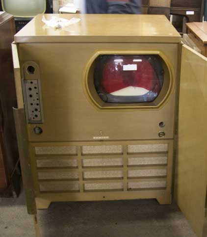
(Picture taken from the Early Television Museum. I believe this to be fair use)
This was the system the FCC mandated for the United States, CBS did broadcast using it, televisions like the above were sold to the public; they were expensive and sales were slow, though. When the Korean War led to domestic color television being paused, the Radio Corporation of America (RCA) was able to lobby to have the decision reconsidered in hopes of providing a more backwards-compatible solution.
And what RCA and the National Television Standards Commission (NTSC) came up with was the same thing that I would plug into my TV fifty years later.
Compatible color
The first thing to note about the NTSC color system (and, in this case, PAL and SECAM too, though they differ in other details) is that the first goal is to preserve a monochrome image that existing TVs can tune into. This means that the majority of the bandwidth is dedicated to the monochrome signal. A color signal, called “chrominance”, is therefore used that does not contain any brightness, and has less bandwidth. How that color is exactly encoded is outside of the scope of this blog post; it’s where much of the difference between NTSC, SECAM, and PAL lie.
The second thing to note is that losing color information is usually totally fine. The human eye is more sensitive to differences in brightness than it is to differences in colors. In fact, we use these tradeoffs even today! Many HDMI devices, even high-end ones that might be under your televsion, use “4:2:2” and even “4:2:0” color spaces. These decrease the horizontal and vertical color resolution, while keeping the brightness at the higher resolution.
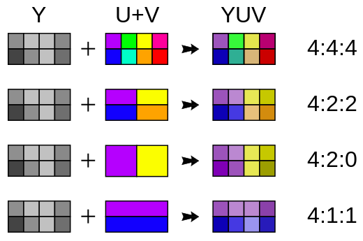
Diagram is from Wikimedia Commons by Stevo-88, and was placed in the public domain.
You can think of composite video as being closer to 4:1:1; two successive lines do not share any data (unlike 4:2:0), but the horizontal color frequency is much lower. Of course, it’s an analog signal, so there are no horizontal pixels per se
This color signal is stored at a higher frequency than the image, and this is where the sacrifice to luminance comes in. But what do I mean by a higher frequency?
The Fourier series
You might wonder how a frequency might have to do with a television signal. It doesn’t exactly look like a sine wave.
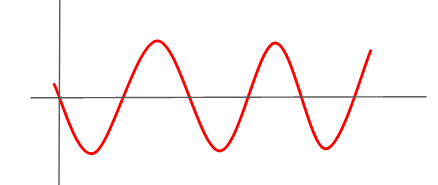
But a Frenchman named Joseph Fourier proved in the 1800s that everything can be sine waves. Essentially, if you sum together higher and higher frequency sine waves of the right amplitude and frequency, you can get back any linear function. And a television signal is a linear function in time. Take this example, which Jacopo Bertolotti kindly gave to Wikimedia Commons.

This is called a Fourier series, specifically a series of sine waves; I don’t feel like doing math beyond this. The key thing to note here, though, is that the frequencies are real. Many electronic parts will operate in what academics call the “frequency domain”; this just means that they care about the frequencies. For example, a “low-pass filter”, which you might have heard about on upscalers, is a filter that passes frequencies below a certain level, but blocks out the high frequency.
If you look at the Batman example above, you can see that the details each higher frequency influences are less and less, but the details get sharper and sharper. So in a picture, you can think of a low pass filter as making an image “fuzzy”. You lose that “infinite” horizontal resolution.
That is the trade-off composite video makes: the higher frequency parts of the image are sacrificed to provide a small amount of color data, which in turn is used to color in the surviving part of the image.
What are the costs of combining luminance and chrominance into a single signal?
When luminance hurts chrominance
So, any “sharp” parts of the image will be “high frequency”. This might make you wonder. Computers have very sharp edges on their text. If you had those dots at just the right width, then those “sharp” parts of the image could be at the right frequency to get interpreted as a color signal.
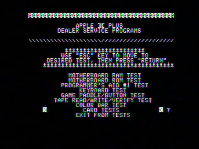
Behold, the Apple ][. The Apple ][’s video resolution of 280x192 was chosen specifically to allow its sharp edges to cause colors; the color resolution you can get out of this is pretty impressive for a computer of 1979. But this is all dot patterns. The tradeoff is that you can always see some color on sharp edges.
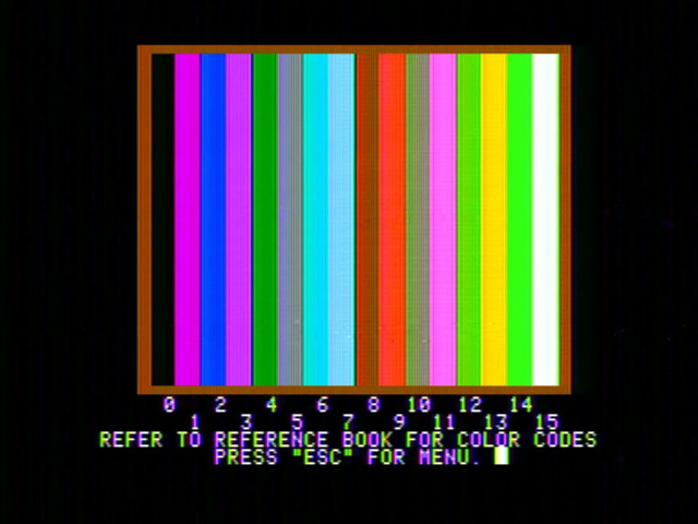
Now, I should note that the text above is a particularly extreme example. You see, when the screen only has text, the Apple ][ contains a “color killer” circuit which is designed to activate the television’s backwards-compatibility mode, and show a monochrome image. The circuit isn’t perfect, though, and it looks like the Micomsoft Framemeister doesn’t have that backwards compatibility mode, causing the bizarre rainbow artifacts.
Amusingly, this is one case where the high-end Framemeister may not be your best option, and a much cheaper “AV2HD” box gets it right.
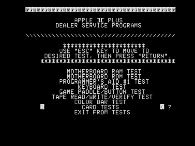
However, the problem with composite video here is that you get these artifacts whether they’re deliberate or not. The Apple ][ times its video specifically to get them and so is the most extreme case, but even on video, the ideal case for composite, it’s still possible to see this “fringing” or “NTSC artifacts”.
PAL and SECAM both use different methods of color encoding that makes these artifacts far less obvious, if visible at all. As a result, in Europe the Apple ][ “Europlus” could only display monochrome video.
When chrominance hurts luminance
One thing that might surprise you is that the opposite can happen too. Chrominance interfering with luminance was, as far as I know, never done deliberately, but it can actually be seen very easily. This impacted both NTSC and PAL; SECAM used a different modulation method which reduced this interference but had its own tradeoffs, which we won’t go into.
Chrominance as used in NTSC and PAL stores its color information in the phase of the high-frequency carrier sine wave. Let’s take the wave above and compare it with one out of phase.
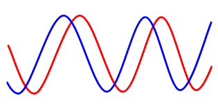
You can see that the two waves look the same, but are moved slightly on the horizontal axis. This change is called a change in “phase”. Because these are sine waves, for trigonometry reasons phase is often expressed as an angle between 0 and 360 degrees.
Now, what does a signal that changes in phase look like?
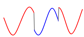
A television’s electronics can pick up on these changes and uses them to color the image. This is a gross oversimplification, though– the carrier waves are “suppressed”, and things can get pretty complicated. But this is the basic concept.
So if a pattern of dots is detected as color, shouldn’t color be detected as dots? The only reason you don’t see this is that televisions are smart and try to filter the color signal. Take this screenshot from Ranma 1/2: Toraware no Hanayome, a PC Engine CD-ROM2 game running on my RGB-modded PC Engine Duo R.

Now, if we plug the composite output of the Pioneer LaserActive into the “Y” jack of the component input of the Open Source Scan Converter (though any high-quality video processor or monitor should work here), we can see what the analog image really looks like without any filtering. Of course, since it’s a luma input, it’ll be monochrome.
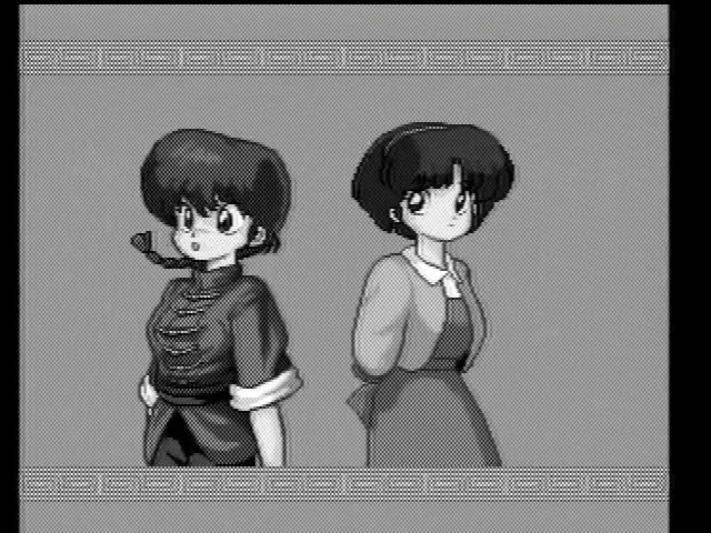
Now, the effect is magnified here because the game is using large swathes of the screen in flat color. But you can see how “compatible color” really did compromise the capabilities of the monochrome signal. The dot pattern looks constant because the frequency of the dots doesn’t change; only the phase does.
The fascinating thing about these “chroma dots”, as they’re called, is that the dots are the color information. The television show Doctor Who had several episodes of the Third Doctor’s era that were broadcast in color, but only survived on film transfers of a monochrome screen. But decades later, the dots in the monochrome screen were used to bring back the color! (The Third Doctor’s era is great by the way, definitely recommend.)
Phase and the “color burst”
So the thing about the “phase” of a sine wave is that it only exists relative to some other wave, or at least some shared starting point. If I just give you a wave sitting in the void, you can’t tell me what its phase is. My TV sitting at home, and the broadcast tower thirty miles away somehow need to come to an agreement about the phase.
This is what a “color burst” does. This is a part of the TV signal in an off-screen part of each line that is used by color TVs to detect color. In NTSC, the color burst is always set as the 180 degree phase, and all phase changes are relative to that. On PAL, different values are used and alternate on each line. (a Phase Alternating Line, if you will) SECAM doesn’t have a color burst.
This is why composite video, especially in NTSC regions, sometimes shows rainbow artifacts, like in the Apple ][ text here. The “color killer” I mentioned makes it hard for the receiver to read the color burst. If you can’t determine the phase, it will look like the phase is always changing, which in turn means the color is always changing. And that’s why you see a rainbow above, whereas in the text without the color killer on (and therefore with a more easily decoded color burst), the artifacts are horizontal.
![finally, the Apple ][DS The two Apple ][ screenshots above, placed together to show text differences described in the paragraph above](/assets/img/composite/apple-ii-2.jpg)
This is why different screens or image processors can make a big difference on whether rainbow banding is present or not; they have different ability to decode the phase, and also in how they separate the video signal.
Separating video
So what should be clear here is that a lot comes down to how a composite video signal is broken down into the two separate chroma and luma signals. Since chrominance is on a 3.58MHz subcarrier (in NTSC regions), this is the frequency you must separate from the rest of the signal, that becomes your luminance. There are two methods that are generally used.
The first, a notch filter, is essentially a combination of a low-pass and high-pass filter. This is probably the most naive approach, and the most common. Because analog video devices may have shifts in their frequency, you often want to include a small range around the subcarrier frequency.
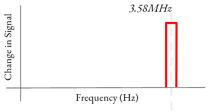
A second method is called a comb filter. In this method, a signal is combined with itself with a very slight delay. Remember Fourier above and that our signal is actually a combination of sine waves. Now, imagine you copy a sine wave, and position it so that the peaks of one wave are at the lowest point of the other.
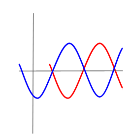
If you sum these together, then the two waves will cancel out perfectly! This is the basic principle of a comb filter; it is named because it not only filters out the target frequency, but any waves that are twice the frequency of the target, or three times the frequency, etc. This makes it a lot like a whole bunch of notch filters; all those notches side by side look like a comb, or at least they do to signal processing engineers.
The advantage of the comb filter is that it is very selective (which means the peaks are narrow), and it captures all the harmonics (the additional higher-frequency peaks) which may be generated. On the other hand, the notch filter captures a slightly wider range, which for some systems like the Nintendo Famicom, which can be out of spec, is considered preferable. Here’s a capture from a Famicom on the RetroTink2X-MINI scaler. First using its comb filter (“Auto”), then with its notch filter (“Retro”).
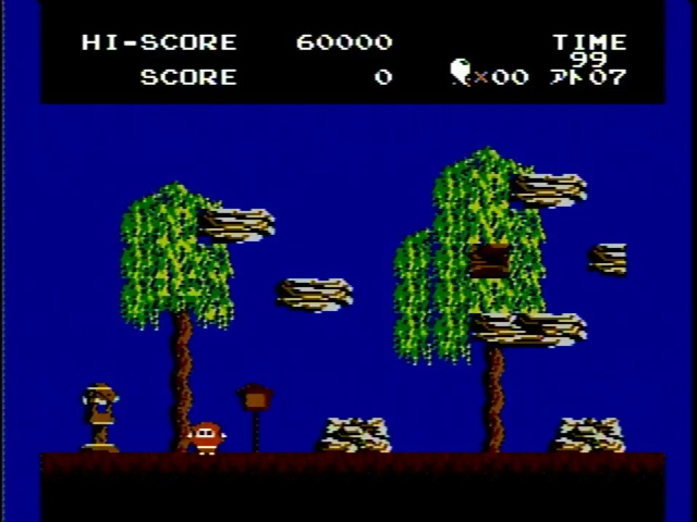
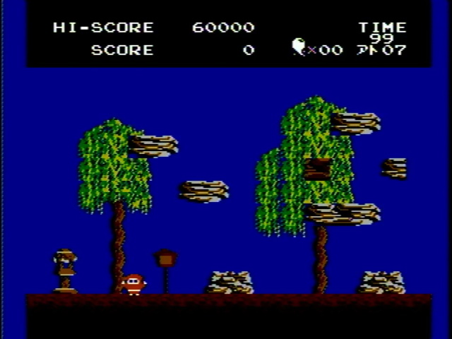
To my eyes, the notch filter definitely increases definition on the trees. The narrower comb filter leaves more of the signal, so things are a bit brighter. Small differences like this are why it can be very hard to determine the “true” color in an NTSC signal; one of the reasons for its nickname, “Never Twice the Same Color”. (This also refers to its tendency to have color phase errors, since the phase doesn’t alternate like in PAL)
The S stands for–
Of course, the luminance-chrominance interference I mentioned above, dot crawl and artifact colors, can be avoided by sending the two signals separately. This “separates” the video; you still have the problems of the lower color resolution, but at least the two signals can’t interfere with each other.
One popular standard that does this is called “S-Video”. This was designed for VHS tapes; VHS tapes also use a combined luminance and chrominance signal, but it provides even less chrominance bandwidth, so it needs to separate the signals to convert it into chrominance a TV can recognize. You can get a slightly better quality output by avoiding a second conversion back to composite.
In North America, S-Video was pretty much the highest-quality television video option you could get during the analog age, as things like component video really only caught on around the beginning of the HD era. Your experience may differ from mine depending on how early of an adopter you were, of course– by the time I got into HD pretty much everything was HDMI.
Europe, meanwhile, had two broadcast color standards: SECAM and PAL. Therefore, any consumer video standard that used broadcast color encoding, be it composite, S-Video, or component, couldn’t be used everywhere. It’s no wonder, therefore, that SCART originated in France. Of course, thanks to globalization, by the 1990s TVs sold in France could usually decode PAL, but by then there was no reason to go backwards, and use of S-Video in Europe seems to be fairly rare.
But…
So this all makes composite video sound pretty bad. But let’s remember a few things.
The Apple ][ is bad
Okay the Apple ][ is one of the greatest and most legendary computers of all time. Its place in history is assured. But, in terms of composite video… it’s bad. It’s deliberately timing its video to get artifacts. Even the later Apple IIgs uses similar video timings on its more advanced modes, and even though it has true color, it gets some bad rainbow artifacting, as I noted in my GBS Control review.
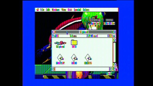
But let’s use the exact same setup to capture the Commodore Amiga 1000, one of only a few Amigae to have a color composite output built-in. Using the same Micomsoft Framemeister, which as noted is prone to rainbow banding issues.
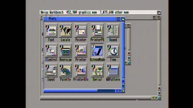
Sure, there’s a bit of color artifacting on the text, but it’s much more readable. And that’s because it’s not deliberately making its pixels the exact width to be prone to NTSC artifacts.
Composite was designed for CRTs
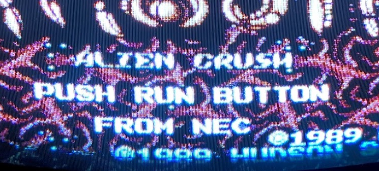
Take a look at the image of the zoomed-in letters above; this is a 90’s consumer TV-VCR that isn’t in great shape. The letters glow, so much so that the text looks rounded. If we use this worn-out tube as a stand-in for the televisions and pre-transistor electronics of a 1950’s television, that additional horizontal resolution wasn’t going to be visible anyway.
Composite was designed for video
This is the big one. I’m using images of early computers and video games to highlight the problems with composite video. But here’s the thing: composite video was designed to capture the real world.
Here’s a picture from that real world; it’s my cat.

Notice that there is a clear distinction between the cat and the ground he stands on. But if we zoom in, and look at the pixels of the above image:

You can see that those harsh edges are not quite there. Sure, some of that is because he is a furry cat. But even on the wood, the grain lines that looked so obvious are not directly corresponding to pixels either. This is because of the cell-phone camera I took it with; but that camera has a much higher resolution than any 480i television camera. Indeed, if we drop it down to composite, most of the quality loss is only because of the reduced resolution, even on the rainbow-loving Framemeister.

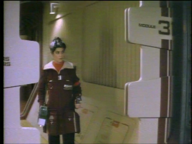
The real world when captured is always a bit fuzzy and low frequency. Sure, there will be some artifacts, but it’s not nearly as obvious. In fact, take a look at this LaserDisc capture from 1983’s Star Trek: The Wrath of Khan. LaserDisc, you might remember, was the high end video option of the 1980’s, and later LaserDiscs would improve on this quality. But when your video looks like this, there’s no need for Blu-ray.
Why composite in 2021?
So, composite video has low color resolution. It’s prone to rainbow artifacts and dot crawl. S-Video makes things a little nicer, but still has that low resolution. Why can’t we throw away our yellow RCA cables just yet?
Analog-era video
The first reason is analog-era video content. The VHS and Laserdisc formats (also called LaserVision, DiscoVision, etc) were the main way people got home video for over twenty years. These formats have content that isn’t available on any other format, ranging from home movies on VHS to even professional content that hasn’t been re-released on a digital format.
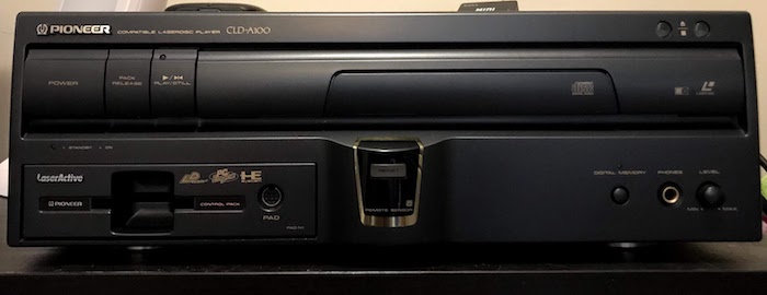
Laserdisc is a composite video format. It’s literally an analog NTSC composite video signal embedded on a disc, usually with a high-quality digital soundtrack aside, sometimes even with surround sound. But the video is composite, and it’s composite in a way you can never upgrade.
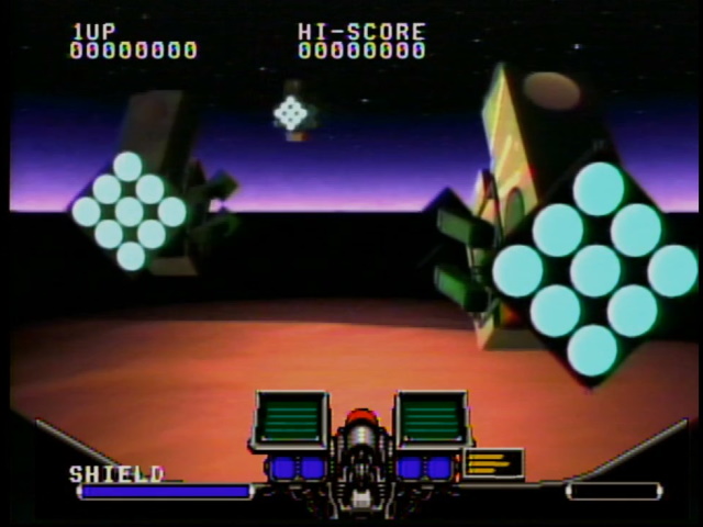
Of course, this also applies to the LaserActive game console; you can RGB mod it, apparently, but it will not give you the LaserDisc video, just the video produced by the console PAC. Those 240p analog backgrounds are composite forever.
Composite color spaces
Many, maybe even most, consoles and computers that used composite video out internally used RGB palettes. For example, the Sega Genesis uses a 9-bit RGB palette; the Neo Geo, a 15-bit RGB with an extra 16th bit used for intensity. (the “dark bit”) Most of these systems had a video chip that output some form of RGB, and then converted it using a separate “RGB encoder” chip like a Sony CXA1145.
In this model, even if a system doesn’t expose its RGB signals (which both the Neo Geo and Sega Genesis did), they can be easily modded to add these to the outside. (Indeed, the CXA1145 has buffered RGB outputs too) But there’s no guarantee a system works like this.
So what do the Atari 2600 (except in France), the Nintendo Famicom, the Commodore 64, and the NEC PC-FX all have in common? All of them are exceptions to the rules I just listed. There is no internal RGB to tap in any of those systems.
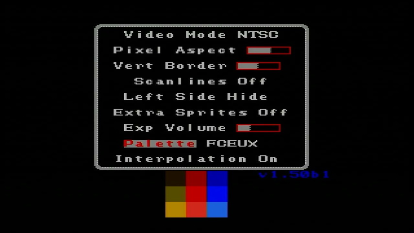
This is why any RGB or HDMI mod for the NES (or in this case, an FPGA recreation) must include a palette. The original palette is encoded directly to create a chroma signal; there’s no RGB equivalent. (In fact, official RGB equivalents of the NES PPU used in the arcades did not line up well with the usual NES palette at all) If you look at the two images of Jajamaru no Daibouken in the comb vs. notch filter section, you can see that even on the same scaler, small settings changes can change the perceived colors, all TVs will be slightly different.
The NES RGB mods you see take advantage of an unused (presumably debug) feature of the NES picture processing unit (PPU); this is a very impressive feat and the creators deserve to be lauded, since the image is still produced by real NES hardware. Commodore fans aren’t so lucky; the only way to get pure RGB for a Commodore 64 is to recreate the entire graphics chip in an FPGA. (However, unlike an unmodded NES, the Commodore 64 can do S-Video, which I’ll talk about more later)
For systems like this, therefore, you may very well prefer to use composite video instead of intrusive mods.
The PC Engine
The PC Engine is an oddball case, so I want to bring it up on its own. Here are two screenshots of the Arcade CD-ROM2 game Fatal Fury 2; the first was taken with an RGB-modded PC Engine Duo R running through the Open-Source Scan Converter. The second was taken with a Pioneer LaserActive PAC-N1 running a low-quality composite upscaler box (the same used with the Apple ][ above).


For one thing, you’ll see that the cheap composite upscaler did a terrible job with the line-by-line effect. That’s something I can talk about more when I talk about upscaling.
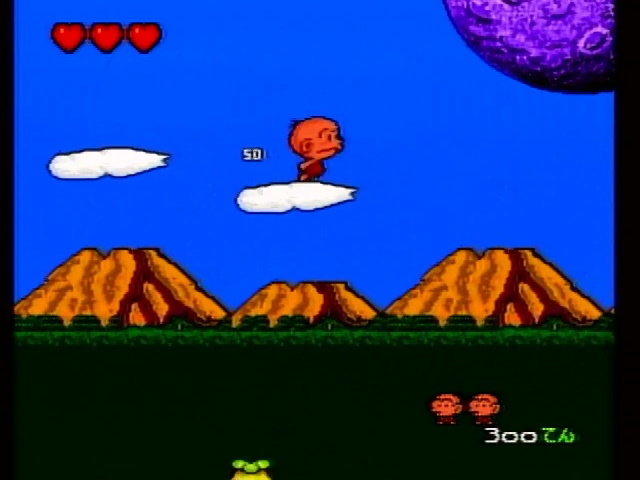
But what’s more important here is the ocean. Notice that with composite video, the blues are darker and the ocean in general blends together much more vividly. This is because the PC Engine, while its Video Color Encoder (VCE) outputs RGB video as used in the modded console, the original composite color outputs are not just simple translations. Hudson used a lookup table to map RGB colors to composite equivalents.


As you can see, this makes a difference to Bonk’s Adventure as well. Which do you like better?
A high-quality S-Video mod is believed possible. Official NEC consoles existed that use both the RGB palette (though only on oddballs like the portable systems) and the composite output only, so to me it’s really a matter of taste. My own PC Engine game, Space Ava 201, was designed using the RGB palette mostly but I made sure would look good and tested in both modes.
The Pioneer LaserActive has its own RGB encoder, so even though it only has composite out, it actually uses the RGB palette when generating that composite. It’s still a little different, but that’s just typical capture artifacts.
Dithering
The Sega Genesis/Mega Drive is well-known for a limited palette; while it has a faster CPU than the PC Engine and multiple scrolling background planes where the TurboGrafx can only do one, it suffered from having only four sixteen color palettes to cover the entire screen. (The little PC Engine punched far above it in weight class with a whopping sixteen 16-color palettes for backgrounds and sixteen more for sprites) The Mega Drive’s colors are basically the same in RGB and composite, since it uses a separate RGB amp.
However, one trick Japanese and American developers used, knowing that the games were likely to be played over composite video with its natural blurring effect, was to use alternating patterns called “dithering”. Take a look at these screenshots from Sonic 3D Blast taken on my Genesis 1 using an RGB cable. (Quite an upgrade over how that Genesis looked over composite in the TMSS article)

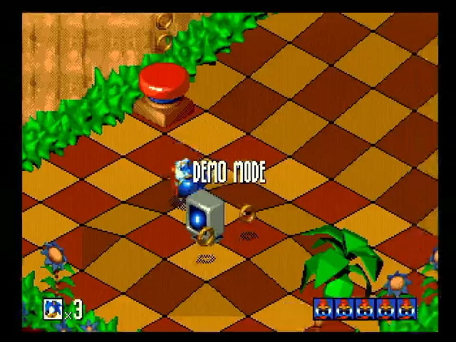
It’s particularly obvious on the pre-rendered 3D title screen, which was pretty popular in that era. Look at those wings around “Blast”, and in the gameplay shot, the mountainside and the shadow underneath Sonic. Now compare them to the Pioneer LaserActive using that same cruddy upscaler box.

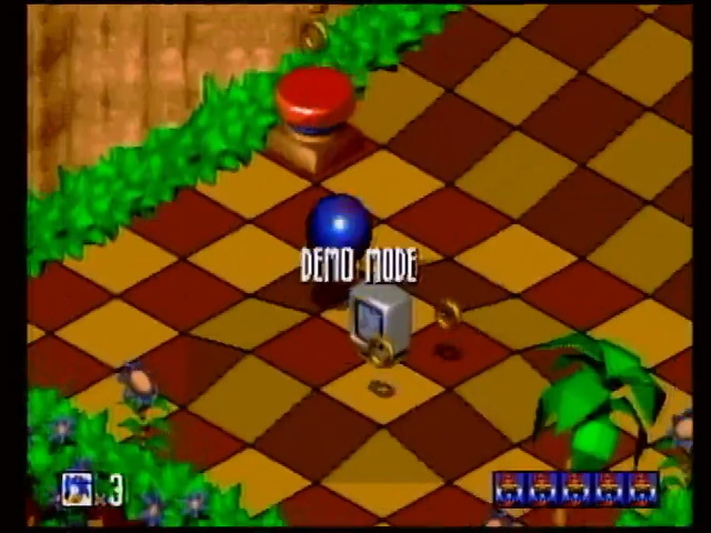
As you can see, those fine pixels are almost gone on this shot. Using dithering not only gets around the 64-color limit, it can also show colors that the Sega’s usual 9-bit RGB could not.
Personally, I still prefer the crisp look, at least when the alternative is this sloppy. But hopefully even this upscaler can give you a glimpse of why many people insist a composite CRT is the real way to play these games. (Here at Nicole Express, of course, we would never advocate that a LaserActive is the correct way to play anything)
S-Video: Actually totally fine!
The final thing to note is that if you separate the luminance and chrominance signals, you now have a full monochrome picture. All of the brightness will be present in the output without artifacts. As for the chrominance, S-Video (as in, the modern standard using a 4-pin mini-DIN) was created for S-VHS, which advertised being able to distinguish 420 visible horizontal lines.
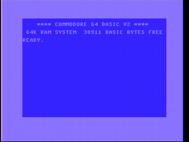
The Commodore 64, meanwhile, has a horizontal resolution of 320 pixels. Even with the border, that should fit comfortably within the limitations of S-Video; and we see that it does in fact look quite crisp, even with colors on the screen, because those blocky pixels are fine. This is from a PAL Commodore 64C.
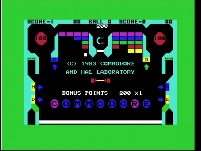
So on the Commodore 64, if your VIC-II has a clean output (they don’t all have one, unfortunately), I don’t know if there’d be much benefit to an RGB mod. Of course, some people won’t be satisfied until they have the most perfect quality possible. But for pixels this large (or, since the horizontal resolution is what matters, this long), you’re going to struggle to see the difference.
This was going to be a composite blog post, but I separated it
I don’t expect you to throw away your PVMs and Frames Meister to go all-out for composite just because of this post; for one thing, most PVMs have a composite input. But I hope it showed why composite video really does have its place, and why you might have reasons to use it other than price. Or, failing that, that it’s a very interesting solution to a technical problem that we really just don’t have anymore. That’s always interesting.
I’d like to now do a comparison of some different composite upscalers, and look at things to look out for and what features you might want to pay attention to. However, this blog post has gotten pretty long, so I think I’ll hold off.
