The Bare Minimum Beats: Panasonic's RD-9844 Rhythm Machine
Recently I’ve had a bit of a fascination with rhythm machines. Not the computerized digital ones like that built into my old Yamaha organ, but fully analog ones. There’s something quite appealing about producing drum-like sounds with just discrete circuits of transistors, capacitors, and resistors. Let’s take a glimpse into a realm so analog that even discrete logic isn’t discrete enough.
Disclaimer: I barely know anything about music. Like, even less than I know about videogames.
An Analogue
In drum machines, “analog” seems to usually mean discrete electronic parts, while “digital” means recordings of instruments that are played back as PCM samples. Of course, today it’s pretty common to have PCM samples (or even more sophisticated recreations in emulation) of analog drum machines on digital machines– in that case I guess “analog” describes more the kind of sound. The kind of sound that might make the “pop” the Mockingboard outputs when you turn on the computer make you think, “hey that could be a drum”.
Well, it takes a little bit more than an audio pop to make a drum. But not that much more.
So for today we’re going to take a look at one particular analog drum machine: the Panasonic RD-9844.
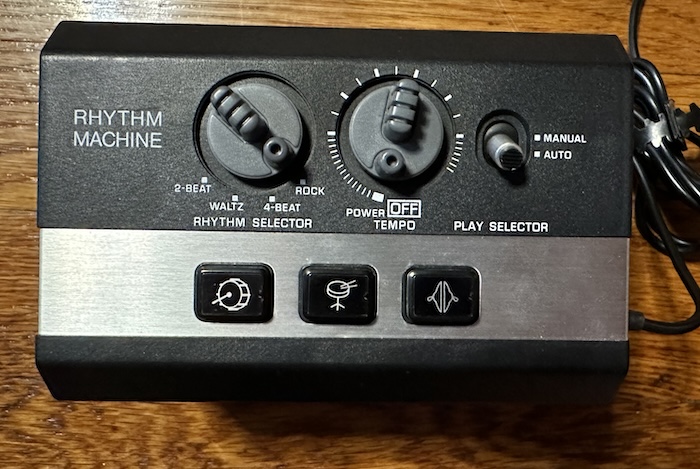
And you might say, why the Panasonic RD-9844 and not something more well-known, like the Roland TR-808, probably the most well-known analog drum machine of all time? I mean, the RD-9844 doesn’t even let you create your own patterns outside of the pitiful four built-in.
- The TR-808 has a microcontroller inside of it that allows for that pattern creation.
- The TR-808’s more sophisticated sounds have more sophisticated circuits. A simpler device is theoretically more easily understood as a didactic device.
- The RD-9844 has a service manual schematic that fits on a single page.
- It’s fun to see how low-end designs solved complex problems with as few parts as possible.
- And most importantly, the TR-808 costs thousands of dollars. The RD-9844 does not. (though on eBay people are already trying to get too much for it)
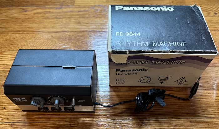
The Panasonic RD-9844 is powered by a 9V battery, with no option for a power plug. A hardwired mono 3.5mm “minijack” plug has the music output on it; mine came with an adapter for 3.5mm to RCA, and I’ve seen the same molded plastic adapter in online listings, so I think it must have come with it. They’re not expecting 6.35mm jacks, which probably says something about the expected users.
Let’s take a quick listen first. Here’s the “rock” preset, which is the most complicated of the bunch. Someone at Panasonic really likes those noise drums, but it’s not just that.
Using the RD-9844
So let’s break the functionality of this simple machine into two parts. A drum machine, and a rhythm machine.
The drum machine
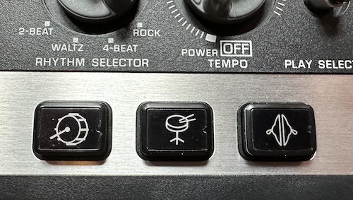
On the front of the Panasonic are three drum pads for the three drum sounds it’s capable of playing. Are they pressure sensitive? Look, I’m going to let you just think about that. Of course they’re not. Be lucky you have them at all.
Bass: it’s not all about it
The first sound worth looking at is the bass drum. Not only is it furthest to the left, and I read from left to right, but this is also the simplest sound that the machine offers. It’s just a decaying wave, triggered by an input pulse.

Here’s an attempt by me to take the schematic, and reduce it to the part that’s only relevant to the bass drum. The audio is input as a pulse generated when you press the button, and the output goes down to the audio frequency amp (AF AMP). This is all transistor logic; the main thing to remember is that on a transistor, if there’s current at the “gate”, current will flow through the other two transistor pins.
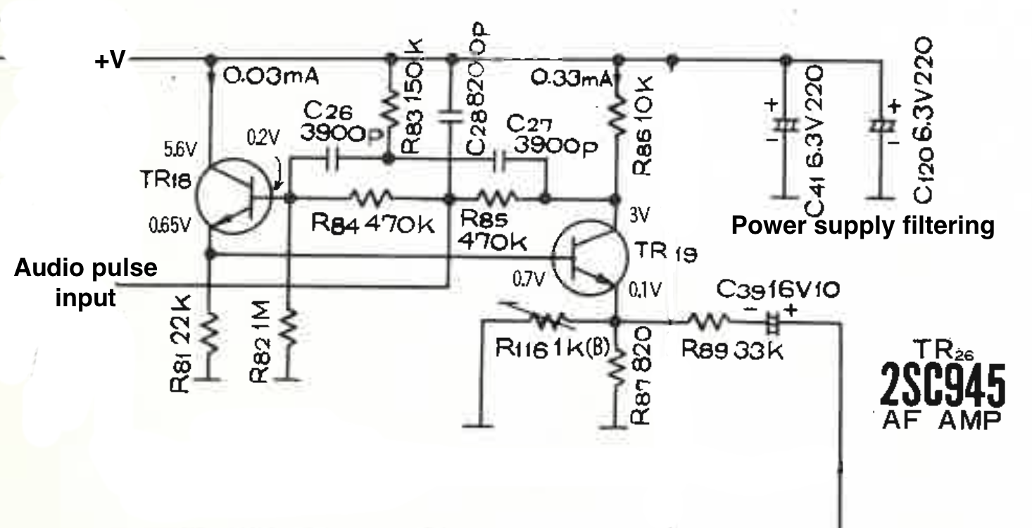
This is a two transistor oscillator. I’m not an expert at analog electronics, but my understanding is that the pulse goes in, and excites the gate of transistor TR18, but only insofar as the RC circuit allows. This allows current to flow through that transistor and through R81 on its way to ground. In turn this current flows through the gate of transistor TR19; this allows current to flow back through R85 and R86 into the gate of TR18, but the additional filters means less and less current flows each time.
For a comparison, here’s the service manual for the aforementioned TR-808. The TR-808 uses an entirely different setup, with op-amp feedback forming a “bridged-T” network, with the same goal of producing a decaying waveform. (thanks to Mickey Delp’s “Anatomy of a Drum Machine” article for pointing me in this direction)
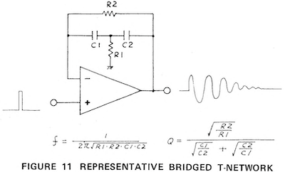
But this makes sense. The Panasonic circuit is simpler, being built out of discrete transistors rather than an op-amp IC, but doesn’t offer as much room for tuning as the TR-808 bass drum does and produces a simpler sound. I’m not sure if Roland had patents on the bridged-T technique, but op-amps were still a rapidly developing technology at the time of this machine.
Cymbal: Out of order

For a cymbal crash, the engineers at Panasonic went pretty straightforward: the trigger pulse is extended out and combined with noise. And that’s it; a burst of noise, filtered a bit by an LC circuit. This is a pretty simple way to do it; the TR-808 is much more sophisticated, combining and filtering the sound of six oscillators. But that’s why it’s funny to compare the two.

The data sheet specs the “noise generator”, TR28, and two “noise amplifiers”, TR24 and TR25. All transistors have some noise, and the 2SC945 mentioned for the noise generator is noisier in its datasheet than the 2SC828 in the amplifiers, but it’s not fatally so; 2SC945s are also specced for the bass drum oscillators above. (The TR-808 is notorious for supposedly using faulty transistors in its noise circuit, giving superstitious analog lovers justification to insist it can never be recreated)
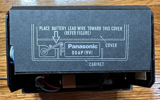
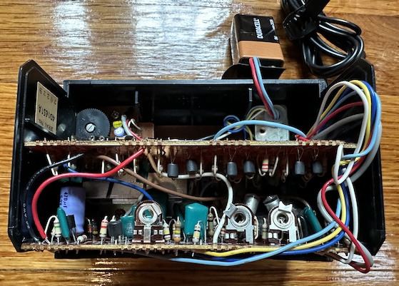
So now I wanted to crack open the circuit and take a look at the transistor setup in person. Now, unfortunately, it turns out that taking this apart is a bit of a pain. What should’ve been obvious to me: this is a compact box filled with discrete parts sold at a low cost. Multiple hand-routed circuitboards connected by various soldered wires. Despite the existence of the repair manual, repairability was not the priority.
Here’s more from the service documents, showing the corner of the lower circuit board where we should find the noise circuit. You can see TR25, C121, and other familiar elements from the schematic.
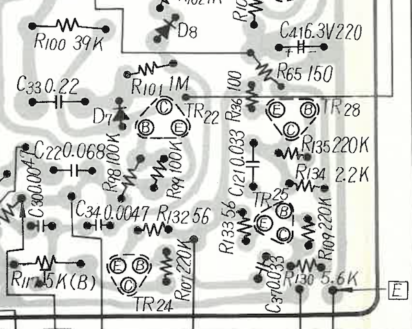
Get your bearings straight; the above diagram is the underside of the circuitboard, while I’m about to show you the top. See TR24 at the left of the variable resistor.
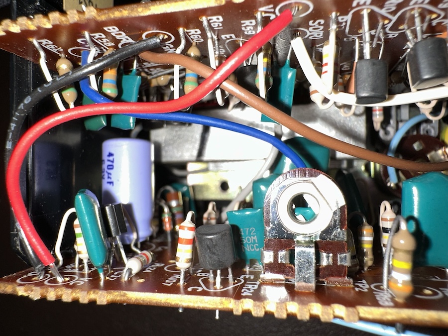
You can see what appears to be TR25. But that 470µF capacitor doesn’t match the value for C121, and behind it is what looks like a diode, not a transistor TR28. TR28 doesn’t seem to be there at all.
My guess is that this must be a later revision of the board, which uses a Zener diode to generate white noise rather than the transistor; maybe Panasonic found it difficult to find transistors with suitable noise behavior. (“Sorry our transistors are just too good” is an interesting problem to have)
Just another reminder to never fully trust service manuals, especially if there are multiple models.
Before we go, let’s take just one more look at that cymbal circuit. From the four-way rhythm selector switch (which turns out to have a ton of contacts), there’s one set of contacts that goes over to the gate of the cymbal, controlling a resistor to ground.
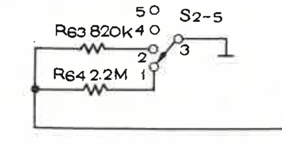
The gating of the cymbal noise (and thus the length of the noise) varies based off of what rhythm you have selected at any given time, even when you’re using manual drum mode. “2-Beat” and “Waltz” are the same, while “4-Beat” and “Rock” have their own versions, both slightly shorter, with 4-Beat shortest of all. Here they are from left to right.
Snare: More like snore?
After all the excitement with the cymbal and bass, we’ve actually seen all the tricks this little drum machine has to offer to generate sound. The snare just combines the two.

It has its own dual transistor decaying oscillator with separate values, and on top of that, its own unique gating (without any per-rhythm variation) to add some noise from the same noise generating circuits. These two components of the snare sound are entirely separate circuits; in fact, if you hammer on the snare button, sometimes you can trigger one but not the other.
These two parts are actually mixed at the same time as everything else; people like to mod vintage drum machines like these to add discrete outputs for each sound, but in this case you could find yourself with four separate outputs.
The rhythm machine
The TR-808 uses a microcontroller to trigger the beats to a user-defined pattern. So we’re done talking about the 808. For the most part, pre-microcontroller analog drum machines, even very nice ones like the Roland TR-77, were limited to preset rhythm patterns. (yes yes your Ace Tone FR-15 is very special) Usually more than four, but this is a pretty low-end machine.
The difficulty of having a number of discrete steps, one after another, shouldn’t be understated. This is what computers were (and still are, unless you get too funny with your out-of-order execution) really good at, but in the analog world, everything happens at once. In fact, the earliest drum machines recognizable as such, like the Wurlitzer Sideman, used a mechanical rotating disk to trigger each step in their patterns. (The arrangeball has a similar mechanism inside, I swear I haven’t forgotten about it)
But the Sideman was made for the vacuum tube era– we have transistors. A big motor and moving metal-on-metal parts might be preferable to using ten tubes’ worth of logic, but ten transistors is far preferable.
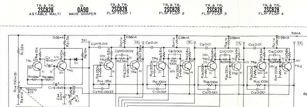
That’s a lot of logic at first glance, but it’s all well labeled. The one thing you’ll need to know is what a flip-flop is; it’s esssentially a single bit of memory, which can be flipped on or off.
- TR1 and TR2 form an astable multivibrator (or a “malti” vibrator– let she who has never made a typo cast the first stone), which is to say, an oscillator. The variable resistor attached to the tempo dial.
- TR3 and TR4 form a flip flop triggered off of the initial oscillator. This essentially divides the frequency in half.
- TR5 and TR6 form a flip flop triggered off of the TR3,4 flip-flops. A flip flop has two outputs;
QandQ', which is just the inverted version. - TR7 and TR8 form, you guessed it, another flip-flop, triggered off of the TR5,6
- Finally, TR9 and TR10 form the last flip-flop.
What this makes is essentially a five-bit binary counter (Digital logic! Our analog purity is gone); each cycle has 32 values in succession. You could also see it as 5 oscillators, each with a frequency half of that of the last. On something like the Rhythm Ace FR-2L, these counters would then enter a “diode matrix”, a grid of diodes where certain signals would be allowed to pass, and that’s what I expected to see on the Panasonic.
So let’s take a look at the schematic again.

In reality, what we see is a resistor matrix. I guess the resistors are sized such that any signal would be sufficiently dissipated if it passed through multiple resistors, but this is a pretty big cost-saving move. I wouldn’t be surprised if ensuring the resistors cause no issues also played a role in choosing the patterns.
There are three wires going out; from top to bottom, these are the triggers for the bass drum, the snare, and the cymbal, respectively. The various switches labeled S2-x are the rhythm select switch; all of these switches are “ganged” and move in unison, but aren’t connected “across” the switches. We’ve already seen S2-5 above.
What do the transistors do? I’ll go from bottom to top.
- TR15 is easy mode. When current flows at the gate, the cymbal fires. Notice that the two bottom inputs of S2-4 are connected; “4-Beat” and “Rock” have the same cymbal patterns.
- TR14 I’ll call the “control” transistor. This transistor doesn’t control anything directly, but if it’s not active, it blocks the path to ground for other transistors.
- TR13 is the snare drum transistor. Its path to ground is always blocked by the TR14 “control” transistor, so both transistors need to fire for the snare drum to fire. You might notice its gate is actually hardwired, the switch S2-3 only matters for the “Waltz” preset.
- TR12, the bass drum transistor, is a little more complex. Notice that S2-1 is grounded for every option except “Rock”. This means that for the other three patterns, it’ll act the same way as the cymbal transistor: signal on the gate, bass drum fires. But for Rock, the path to ground passes through TR14, so it acts like the snare, needing current to be flowing at the gates of both TR12 and TR14. (I think R60 is high enough resistance that it doesn’t matter here, and is probably just to avoid anything floating)
The role of the control transistor is a lot like an AND gate. Both TR14 AND TR13 need to have current for a snare drum to fire. For the “Rock” preset, both TR14 AND TR12 need to have current for a bass drum to fire. With this logic in place, you can trace out all the beat patterns.
Waltz
The “waltz” mode is the most interesting one. Not because I’m a huge fan of the waltz, but because of the time signature. Every other preset has an even number of beats per measure. 2:2 time, 4:4 time, it doesn’t really matter– what matters is the number of beats fits cleanly into 32. But a waltz practically by definition is 3:4 time– three quarter note beats per measure. No total number produced by a binary counter is divisible by three, and that includes 32.
So I assumed that logically, there must be some sort of logic to reset the counter early, yet I didn’t see any on the schematic. But let’s take a look at the times of the Waltz preset in my recording.
| t (s) | t / ttotal | (t / ttotal) * 32 | |
|---|---|---|---|
| Beat 1 | 0 | 0 | 0 |
| Beat 2 | 0.85 | 0.35 | 11 |
| Beat 3 | 1.69 | 0.68 | 22 |
| Next | 2.46 | 1.00 | 32 |
And we see that the RD-9844 just sacrifices exact timing instead. Going up to 32 means that it’s only a little bit off, a single 32nd note. That’ll still add up over time, and it does sound just a little off to me. And yet I’m fairly certain this “Waltz” preset is the only thing that uses the least significant bit; the other three patterns just use the 16-value or fewer counters.
It’s worth noting that while all these timing systems work, I notice that if you hit the buttons while the presets are playing, it can foul up the timing, or even just switching between presets will sometimes fire a drum. (Especially likely with “Waltz”, for some reason) So this is clearly built to a price; some reliability is sacrificed in favor of low-cost.
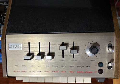
I actually have another vintage analog drum machine, the Univox SR-95, the US rebadge (with some tweaks) of the Keio (Korg) Mini Pops 7. (Used by Jean-Michel Jarre in Oxygène, among others) I got this for my organ playing, but if people are interested, it might be worth taking a look how a higher-cost machine solved the same problems.
Panasonic RD-9844
I’m not actually sure when the Panasonic RD-9844 came out. Mine came with a box and a Panasonic catalog, and I notice that they’re advertising the NV-2110/NV-2120/NV-2125 “U-Vision” (Panasonic’s branding for U-Matic) videocassette system, as well as the NV-5110/NV-5120/NV-5125 video recorders, which I believe used a different system. The NV-5130 is presumably not out yet, and Radiomuseum dates that model (with two question marks) to 1976. So at least this one probably dates to the first half of the 1970s. Pretty modern design for then, with the black and silver plastic. (That’s half a decade or more before the TR-808, for those taking notes)
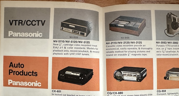
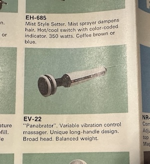
The Panasonic catalog in itself is a lot of fun. Panasonic basically sold everything in those days, so if you liked their rhythm machine and now wanted a VCR, a color TV, a refrigerator, a vacuum cleaner, a car stereo, or a washing machine, they were hoping that they could sell it to you. Even a personal massager, if you’re worn out after a long day of pushing your Panasonic vacuum cleaner around.
